Lexus RX (RX 350L, RX450h) 2016-2026 Repair Manual: Speedometer Malfunction
DESCRIPTION
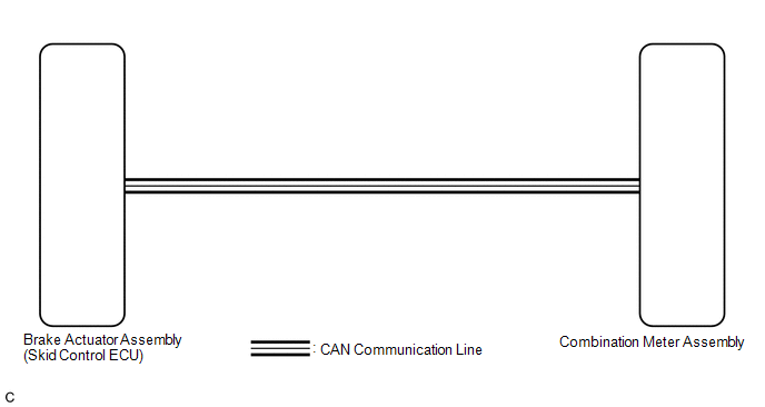
The combination meter assembly receives vehicle speed signals from the brake actuator assembly (skid control ECU) via CAN communication. The speed sensor detects the wheel speed and sends the appropriate signals to the brake actuator assembly (skid control ECU). The brake actuator assembly (skid control ECU) supplies power to the vehicle speed sensor. The brake actuator assembly (skid control ECU) detects vehicle speed signals based on pulses of the voltage.
HINT:
-
Factors that affect the indicated vehicle speed include the tire size, tire inflation, and tire wear. The speed indicated on the speedometer has an allowable margin of error. This can be tested using the Techstream. For details about testing and the margin of error, see the reference chart.
Click here
.gif)
-
If the vehicle speed sensor circuit has a malfunction, the brake actuator assembly (skid control ECU) stores DTCs. Troubleshoot the vehicle stability control system.
Click here
WIRING DIAGRAM
CAUTION / NOTICE / HINT
NOTICE:
- When replacing the combination meter assembly, always replace it with a new one. If a combination meter assembly which was installed to another vehicle is used, the information stored in it will not match the information from the vehicle and a DTC may be stored.
-
If the vehicle speed is outside the allowable range when tested, perform the on-vehicle inspection.
Click here
HINT:
- Before starting the following inspection, check tire size and tire air pressure.
- Active Test cannot be performed on the speedometer for TFT meter type.
PROCEDURE
| 1. | CHECK CAN COMMUNICATION SYSTEM |
(a) Check if CAN communication DTCs are output.
Click here
| Result | Proceed to |
|---|---|
| CAN communication DTCs are not output. | A |
| CAN communication DTCs are output. | B |
| B | .gif) | GO TO CAN COMMUNICATION SYSTEM |
|
.gif)
| 2. | CONFIRM MODEL |
(a) Choose the model to be inspected.
| Result | Proceed to |
|---|---|
| for Optitron Meter Type | A |
| for TFT Meter Type | B |
| B | | GO TO STEP 4 |
|
| 3. | PERFORM ACTIVE TEST USING TECHSTREAM (SPEED METER OPERATION) |
(a) Connect the Techstream to the DLC3.
(b) Turn the engine switch on (IG).
(c) Turn the Techstream on.
(d) Enter the following menus: Body Electrical / Combination Meter / Active Test.
(e) Perform the Active Test according to the display on the Techstream.
Body Electrical > Combination Meter > Active Test| Tester Display | Measurement Item | Control Range | Diagnostic Note |
|---|---|---|---|
| Speed Meter Operation | Speedometer |
| There is a deviation in the values displayed on the speedometer (Control range → Speedometer display) for Optitron Meter Type (mph)*1:
for Optitron Meter Type (km/h)*2:
|
- *1: for Speedometer with Imperial Units Main Scale
- *2: for Speedometer with Metric Units Main Scale
| Tester Display |
|---|
| Speed Meter Operation |
OK:
Speedometer indication is normal.
| NG | | REPLACE COMBINATION METER ASSEMBLY |
|
| 4. | CHECK FOR DTC |
(a) Check if vehicle stability control system DTCs are output.
Click here
| Result | Proceed to |
|---|---|
| Vehicle stability control system DTCs are not output. | A |
| Vehicle stability control system DTCs are output. | B |
| B | | GO TO VEHICLE STABILITY CONTROL SYSTEM |
|
| 5. | READ VALUE USING TECHSTREAM (VEHICLE SPEED, VEHICLE SPEED METER) |
(a) Connect the Techstream to the DLC3.
(b) Turn the engine switch on (IG).
(c) Turn the Techstream on.
(d) Enter the following menus:
(1) for ABS/VSC/TRC/EPB: Chassis / ABS/VSC/TRC/EPB / Data List.
(2) for Combination Meter: Body Electrical / Combination Meter / Data List.
(e) Read the Data List according to the display on the Techstream.
Chassis > Brake/EPB > Data List| Tester Display | Measurement Item | Range | Normal Condition | Diagnostic Note |
|---|---|---|---|---|
| Vehicle Speed | Maximum wheel speed sensor reading | Min.: 0 km/h (0 mph), Max.: 6553.5 km/h (4072 mph) | Vehicle stopped: 0 km/h (0 mph) | When driving at constant speed: No large fluctuations |
| Tester Display |
|---|
| Vehicle Speed |
| Tester Display | Measurement Item | Range | Normal Condition | Diagnostic Note |
|---|---|---|---|---|
| Vehicle Speed Meter | Vehicle speed | Min.: 0 km/h (0 mph), Max.: 255 km/h (158 mph) | Almost the same as actual vehicle speed | - |
| Tester Display |
|---|
| Vehicle Speed Meter |
| Result | Proceed to |
|---|---|
| The Data List values of the ECUs match. | A |
| The Data List values of the ECUs do not match. | B |
HINT:
- When the Data List values of the ECUs match, an internal malfunction of the combination meter assembly is suspected.
- When the Data List values of the ECUs do not match, a signal output malfunction of the brake actuator assembly (skid control ECU) or an internal malfunction of the combination meter assembly is suspected.
| A | | REPLACE COMBINATION METER ASSEMBLY |
|
| 6. | REPLACE COMBINATION METER ASSEMBLY |
(a) Replace the combination meter assembly with a new one.
Click here
OK:
The operation of the speedometer returns to normal.
| OK | | END |
| NG | | REPLACE BRAKE ACTUATOR ASSEMBLY (SKID CONTROL ECU) |
 Lost Communication with ECM / PCM "A" (U0100,U0129,U0131,U0140,U0151,U0163,U0182,U023A)
DESCRIPTION The combination meter assembly communicates with the ECM, brake actuator assembly (skid control ECU), power steering ECU assembly, main body ECU (multiplex network body ECU), airbag sensor ...
 Tachometer Malfunction
DESCRIPTION In this circuit, the combination meter assembly receives engine speed signals from the ECM via CAN communication. The combination meter assembly displays the engine speed calculated based ...
Other materials:
Lexus RX (RX 350L, RX450h) 2016-2026 Repair Manual > Back Door Courtesy Switch: Inspection
INSPECTION PROCEDURE 1. INSPECT BACK DOOR LOCK ASSEMBLY *a Clockwise *b Counterclockwise *c Over-latch *d Full-latch *e Half-latch *f Open-latch *g Component without harness connected (Back Door Lock Assembly) (a) Apply battery voltage to the door lock mo ...
Lexus RX (RX 350L, RX450h) 2016-2026 Repair Manual > Rear Power Seat Control System(for Second Row): Operation Check
OPERATION CHECK CHECK BASIC FUNCTION HINT: The rear power seat switch is a collective term for the rear power seat switch RH and the rear power seat switch LH. (a) Operate the rear power seat switch, fold seat switch assembly and check that each switch function operates normally.
Reclining operat ...
Lexus RX (RX 350L, RX450h) 2016-{YEAR} Owners Manual
- For your information
- Pictorial index
- For safety and security
- Instrument cluster
- Operation of each component
- Driving
- Lexus Display Audio system
- Interior features
- Maintenance and care
- When trouble arises
- Vehicle specifications
- For owners
Lexus RX (RX 350L, RX450h) 2016-{YEAR} Repair Manual

0.0101