Lexus RX (RX 350L, RX450h) 2016-2026 Repair Manual: Switch Lights of Remote Touch do not Illuminate
DESCRIPTION
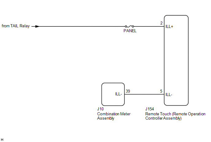
Power is supplied to the remote touch (remote operation controller assembly) illumination when the light control switch is in the tail or head position.
WIRING DIAGRAM
CAUTION / NOTICE / HINT
NOTICE:
Inspect the fuse for circuits related to this system before performing the following procedure.
PROCEDURE
| 1. | CHECK SYMPTOMS |
| (a) Perform the following procedure and check the switch illumination again. (1) If the vehicle is in a bright area, move it to a dark area. HINT: When the vehicle is in a bright area, the switch illumination may not turn on due to the automatic dimmer function. (2) Set the rheostat to maximum brightness. HINT: If the brightness of the rheostat is set to low, switch illumination may not be recognized even when the switch illumination turns on. (3) If the light control switch is in the AUTO position, turn the switch to the tail or head position. HINT: If the light control switch is in the AUTO position, the switch illumination will not turn on unless the surrounding area is dark. OK: Switch illumination turns on. |
|
.png)
| OK |  | END |
|

| 2. | REMOTE TOUCH (REMOTE OPERATION CONTROLLER ASSEMBLY) SELF CHECK (SWITCH ILLUMINATION CHECK) |
(a) Enter self-diagnostic mode.
Click here .gif)
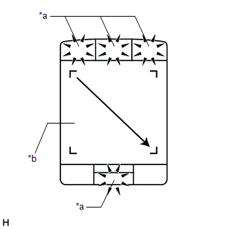
| (b) Operate the remote touch screen diagonally from the upper left to the lower right and check that the brightness of the switch illumination changes. NOTICE: Since the remote touch screen may recognize a pinch in/out or flick operation if operated with 2 fingers, always use 1 finger to operate the remote touch screen in self-diagnostic mode. OK: Brightness changes according to remote touch screen operation. |
|
| NG | | REPLACE REMOTE TOUCH (REMOTE OPERATION CONTROLLER ASSEMBLY) |
|
| 3. | CHECK HARNESS AND CONNECTOR (ILLUMINATION SIGNAL CIRCUIT) |
(a) Disconnect the J154 remote touch (remote operation controller assembly) connector.
(b) Measure the voltage according to the value(s) in the table below.
Standard Voltage:
| Tester Connection | Condition | Specified Condition |
|---|---|---|
| J154-2 (ILL+) - Body ground | Light control switch in tail or head position | 11 to 14 V |
| NG | | REPAIR OR REPLACE HARNESS OR CONNECTOR |
|
| 4. | CHECK HARNESS AND CONNECTOR (REMOTE TOUCH (REMOTE OPERATION CONTROLLER ASSEMBLY) - COMBINATION METER ASSEMBLY) |
(a) Disconnect the J154 remote touch (remote operation controller assembly) connector.
(b) Disconnect the J10 combination meter assembly connector.
(c) Measure the resistance according to the value(s) in the table below.
Standard Resistance:
| Tester Connection | Condition | Specified Condition |
|---|---|---|
| J154-5 (ILL-) - J10-39 (ILL-) | Always | Below 1 Ω |
| J154-5 (ILL-) or J10-39 (ILL-) - Body ground | Always | 10 kΩ or higher |
| NG | | REPAIR OR REPLACE HARNESS OR CONNECTOR |
|
| 5. | REPLACE REMOTE TOUCH (REMOTE OPERATION CONTROLLER ASSEMBLY) |
(a) Replace the remote touch (remote operation controller assembly) with a new or known good one.
Click here
(b) Check if the switch illumination turns on.
OK:
The switch illumination turns on when the light control switch is in the tail or head position.
| OK | | END |
| NG | | GO TO METER / GAUGE SYSTEM |
 Remote Touch Screen Does not Generate Vibration Feedback
DESCRIPTION When each button displayed on the multi-display assembly is selected via remote touch screen operation, the remote touch screen generates vibration feedback according to communication betw ...
 Switch Lights of Remote Touch Always Illuminate or cannot be Controlled Using Rheostat
DESCRIPTION Power is supplied to the remote touch (remote operation controller assembly) illumination when the light control switch is in the tail or head position. HINT:
When the remote touch (rem ...
Other materials:
Lexus RX (RX 350L, RX450h) 2016-2026 Repair Manual > Instrument Panel Safety Pad: Precaution
PRECAUTION PRECAUTION FOR VEHICLE WITH SRS AIRBAG AND SEAT BELT PRETENSIONER (a) Some operations in this section may affect the SRS parts. Prior to performing the corresponding operations, read the precautions regarding the SRS parts. Click here TABLE OF BOLT, SCREW AND NUT HINT: All bolts, screws ...
Lexus RX (RX 350L, RX450h) 2016-2026 Repair Manual > Vehicle Stability Control System: Test Mode Procedure
TEST MODE PROCEDURE ACTIVATE DEALER MODE (SIGNAL CHECK) HINT:
Signals related to the vehicle stability control system can be inspected by performing a Dealer Mode (Signal Check) inspection. During the inspection, the display of items determined normal by the skid control ECU (brake actuator assem ...
Lexus RX (RX 350L, RX450h) 2016-{YEAR} Owners Manual
- For your information
- Pictorial index
- For safety and security
- Instrument cluster
- Operation of each component
- Driving
- Lexus Display Audio system
- Interior features
- Maintenance and care
- When trouble arises
- Vehicle specifications
- For owners
Lexus RX (RX 350L, RX450h) 2016-{YEAR} Repair Manual

0.0108