Lexus RX (RX 350L, RX450h) 2016-2026 Repair Manual: Folding Motor Circuit
DESCRIPTION
HINT:
- The rear power seat switch is a collective term for the rear power seat switch RH and the rear power seat switch LH.
- The rear seatback frame sub-assembly is a collective term for the rear seatback frame sub-assembly RH and the rear seatback frame sub-assembly LH.
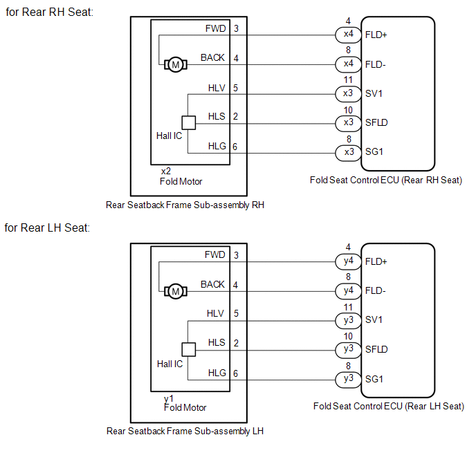
The fold seat control ECU receives switch operation signals from the rear power seat switch and fold seat switch assembly operates the fold motor according to the received signal. While the fold motor is operating, its built-in Hall IC detects the position of the rear seatback and sends a fold motor position sensor signal to the fold seat control ECU. The fold seat control ECU uses the Hall IC to detect abnormalities, such as if the rear seatback is jammed.
WIRING DIAGRAM
PROCEDURE
| 1. | INSPECT REAR SEATBACK FRAME SUB-ASSEMBLY (FOLD MOTOR) |
(a) Remove the rear seatback frame sub-assembly.
-
for Rear LH Seat: Click here
.gif)
-
for Rear RH Seat: Click here
(b) Inspect the rear seatback frame sub-assembly (fold motor).
-
for Rear LH Seat: Click here
-
for Rear RH Seat: Click here
| NG | .gif) | REPLACE REAR SEATBACK FRAME SUB-ASSEMBLY |
|
.gif)
| 2. | CHECK HARNESS AND CONNECTOR (FOLD SEAT CONTROL ECU - FOLD MOTOR) |
(a) Disconnect the x3*1 or y3*2 and x4*1 or y4*2 fold seat control ECU (rear RH seat) connectors.
- *1: for Rear RH Seat
- *2: for Rear LH Seat
(b) Disconnect the x2*1 or y1*2 fold motor connector.
- *1: for Rear RH Seat
- *2: for Rear LH Seat
(c) Measure the resistance according to the value(s) in the table below.
Standard Resistance:
for Rear RH Seat
| Tester Connection | Condition | Specified Condition |
|---|---|---|
| x3-11 (SV1) - x2-5 (HLV) | Always | Below 1 Ω |
| x3-11 (SV1) or x2-5 (HLV) - Body ground | Always | 10 kΩ or higher |
| x3-10 (SFLD) - x2-2 (HLS) | Always | Below 1 Ω |
| x3-10 (SFLD) or x2-2 (HLS) - Body ground | Always | 10 kΩ or higher |
| x3-8 (SG1) - x2-6 (HLG) | Always | Below 1 Ω |
| x3-8 (SG1) or x2-6 (HLG) - Body ground | Always | 10 kΩ or higher |
| x4-4 (FLD+) - x2-3 (FWD) | Always | Below 1 Ω |
| x4-4 (FLD+) or x2-3 (FWD) - Body ground | Always | 10 kΩ or higher |
| x4-8 (FLD-) - x2-4 (BACK) | Always | Below 1 Ω |
| x4-8 (FLD-) or x2-4 (BACK) - Body ground | Always | 10 kΩ or higher |
for Rear LH Seat
| Tester Connection | Condition | Specified Condition |
|---|---|---|
| y3-11 (SV1) - y1-5 (HLV) | Always | Below 1 Ω |
| y3-11 (SV1) or y1-5 (HLV) - Body ground | Always | 10 kΩ or higher |
| y3-10 (SFLD) - y1-2 (HLS) | Always | Below 1 Ω |
| y3-10 (SFLD) or y1-2 (HLS) - Body ground | Always | 10 kΩ or higher |
| y3-8 (SG1) - y1-6 (HLG) | Always | Below 1 Ω |
| y3-8 (SG1) or y1-6 (HLG) - Body ground | Always | 10 kΩ or higher |
| y4-4 (FLD+) - y1-3 (FWD) | Always | Below 1 Ω |
| y4-4 (FLD+) or y1-3 (FWD) - Body ground | Always | 10 kΩ or higher |
| y4-8 (FLD-) - y1-4 (BACK) | Always | Below 1 Ω |
| y4-8 (FLD-) or y1-4 (BACK) - Body ground | Always | 10 kΩ or higher |
| NG | | REPAIR OR REPLACE HARNESS OR CONNECTOR |
|
| 3. | CHECK REAR SEATBACK FRAME SUB-ASSEMBLY (POSITION SENSOR) |
(a) Temporarily replace the rear seatback frame sub-assembly with a new or known good one.
-
for Rear LH Seat: Click here
-
for Rear RH Seat: Click here
(b) Check the operation of the rear power seat.
Click here
| OK | | END (REAR SEATBACK FRAME SUB-ASSEMBLY WAS DEFECTIVE) |
| NG | | REPLACE FOLD SEAT CONTROL ECU |
 Power Source Circuit
DESCRIPTION Power is supplied to the fold seat control ECU through the ECU-DCC NO. 2, P/SEAT R/R*1, P/SEAT R/L*2 and ECU-IG1 NO. 4 fuses.
*1: for Rear Right Seat
*2: for Rear Left Seat
WIRING ...
 Reclining Motor Circuit
DESCRIPTION HINT:
The rear power seat switch is a collective term for the rear power seat switch RH and the rear power seat switch LH.
The rear seatback frame sub-assembly is a collective term fo ...
Other materials:
Lexus RX (RX 350L, RX450h) 2016-2026 Repair Manual > Power Mirror Control System (w/o Memory): Data List / Active Test
DATA LIST / ACTIVE TEST DATA LIST HINT: Using the Techstream to read the Data List allows the values or states of switches, sensors, actuators and other items to be read without removing any parts. This non-intrusive inspection can be very useful because intermittent conditions or signals may be dis ...
Lexus RX (RX 350L, RX450h) 2016-2026 Repair Manual > Intelligent Clearance Sonar System: Brake System (C1A50)
DESCRIPTION When a vehicle stability control system malfunction signal sent from the skid control ECU assembly is detected by the clearance warning ECU assembly, DTC C1A50 is stored. DTC No. Detection Item DTC Detection Condition Trouble Area C1A50 Brake System When the engine switc ...
Lexus RX (RX 350L, RX450h) 2016-{YEAR} Owners Manual
- For your information
- Pictorial index
- For safety and security
- Instrument cluster
- Operation of each component
- Driving
- Lexus Display Audio system
- Interior features
- Maintenance and care
- When trouble arises
- Vehicle specifications
- For owners
Lexus RX (RX 350L, RX450h) 2016-{YEAR} Repair Manual

0.0127