Lexus RX (RX 350L, RX450h) 2016-2026 Repair Manual: Terminals Of Ecu
TERMINALS OF ECU
CHECK FOLD SEAT CONTROL ECU (RH SEAT)

(a) Disconnect the x15 and x16 fold seat control ECU (RH seat) connectors.
(b) Measure the resistance and voltage according to the value(s) in the table below.
| Terminal No. (Symbol) | Wiring Color | Terminal Description | Condition | Specified Condition |
|---|---|---|---|---|
| x16-2 (+B) - Body ground | W - Body ground | Battery power supply | Always | 11 to 14 V |
| x16-1 (IND1) - Body ground | B - Body ground | Battery power supply | Always | 11 to 14 V |
| x15-1 (ECUB) - Body ground | W - Body ground | System power source | Always | 11 to 14 V |
| x15-3 (IG) - Body ground | B - Body ground | IG switch signal | Engine switch off | Below 1 V |
| IG switch signal | Engine switch on (IG) | 11 to 14 V | ||
| x16-10 (GND) - Body ground | W-B - Body ground | Ground | Always | Below 1 Ω |
| x16-9 (GND2) - Body ground | W-B - Body ground | IG switch signal | Always | Below 1 Ω |
| x15-40 (IND2) - Body ground | W-B - Body ground | System ground | Always | Below 1 Ω |
(c) Reconnect the x15 and x16 fold seat control ECU (RH seat) connectors.
(d) Measure the resistance and voltage according to the value(s) in the table below.
(e) Using an oscilloscope, check the waveform.
| Terminal No. (Symbol) | Wiring Color | Terminal Description | Condition | Specified Condition |
|---|---|---|---|---|
| x16-4 (FLD+) - Body ground | L - Body ground | Lifter motor operation signal (Fold) | Fold switch (RH) of fold seat switch assembly or No. 1 fold seat switch assembly released → pushed (Fold operation) | Below 1 V → 11 to 14 V |
| x16-8 (FLD-) - Body ground | SB - Body ground | Lifter motor operation signal (Return) | Return switch (RH) of fold seat switch assembly or No. 1 fold seat switch assembly released → pushed (Return operation) | Below 1 V → 11 to 14 V |
| x15-11 (SV1) - x15-8 (SG1) | R - G | Lifter motor position sensor power source | Engine switch off → Engine switch on (IG) | Below 1 V → 5.5 to 10 V |
| x15-10 (SFLD) - x15-8 (SG1) | P - G | Lifter motor position sensor signal | Lifter motor (RH) operating (Fold/return operation) | Pulse generation (Hi: 5.5 to 10 V, Lo: Below 1 V) |
| x15-8(SG1) - Body ground | G - Body ground | Lifter motor position sensor ground | Always | Below 1 Ω |
| x16-3 (RCL+) - Body ground | L - Body ground | Reclining motor operation signal (Fold) | Fold switch (RH) of fold seat switch assembly or No. 1 fold seat switch assembly released → pushed (Fold operation) | Below 1 V → 11 to 14 V |
| x16-7 (RCL-) - Body ground | SB - Body ground | Reclining motor operation signal (Fold) | Return switch (RH) of fold seat switch assembly or No. 1 fold seat switch assembly released → pushed (Return operation) | Below 1 V → 11 to 14 V |
| x15-31 (SV2) - x15-28 (SG2) | R - G | Reclining motor position sensor power source | Engine switch off → Engine switch on (IG) | Below 1 V → 5.5 to 10 V |
| x15-9 (SRCL) - x15-28 (SG2) | P - G | Reclining motor position sensor signal | Reclining motor (RH) operating (Fold/return operation) | Pulse generation (Hi: 5.5 to 10 V, Lo: Below 1 V) |
| x15-28 (SG2) - Body ground | G - Body ground | Reclining motor position sensor ground | Always | Below 1 Ω |
| x15-25 (RCLR) - Body ground | B - Body ground | Fold seat switch assembly (return switch (RH)) operation signal | Return switch (RH) of fold seat switch assembly released → pushed | 11 to 14 V → Below 1 V |
| x15-26 (RCLF) - Body ground | L - Body ground | Fold seat switch assembly (fold switch (RH)) operation signal | Fold switch (RH) of fold seat switch assembly released → pushed | 11 to 14 V → Below 1 V |
| x15-7 (RTRN) - Body ground | B - Body ground | Fold seat switch assembly (return switch (RH)) operation signal | Return switch (RH) of No. 1 fold seat switch assembly released → pushed | 11 to 14 V → Below 1 V |
| x15-12 (FOLD) - Body ground | L - Body ground | Fold seat switch assembly (fold switch (RH)) operation signal | Fold switch (RH) of No. 1 fold seat switch assembly released → pushed | 11 to 14 V → Below 1 V |
| x15-17 (P) - Body ground | GR - Body ground | Driving condition signal | Any of the following conditions are met:
| 11 to 14 V |
| Engine switch is on (IG) and any of the following conditions are met:
| Below 1 V | |||
| x15-18 (R CL) - Body ground | P - Body ground | Rear door courtesy light switch assembly (RH) input signal | Rear door RH open → closed | Below 1 V → 11 to 14 V |
| x15-19 (BDCY) - Body ground | R - Body ground | Back door courtesy light switch assembly input signal | Back door open → closed | Below 1 V → 11 to 14 V |
CHECK FOLD SEAT CONTROL ECU (LH SEAT)

(a) Disconnect the y15 and y16 fold seat control ECU (LH seat) connectors.
(b) Measure the resistance and voltage according to the value(s) in the table below.
| Terminal No. (Symbol) | Wiring Color | Terminal Description | Condition | Specified Condition |
|---|---|---|---|---|
| y16-2 (+B) - Body ground | W - Body ground | Battery power supply | Always | 11 to 14 V |
| y16-1 (IND1) - Body ground | B - Body ground | Battery power supply | Always | 11 to 14 V |
| y15-1 (ECUB) - Body ground | W - Body ground | System power source | Always | 11 to 14 V |
| y15-3 (IG) - Body ground | B - Body ground | IG switch signal | Engine switch off | Below 1 V |
| Engine switch on (IG) | 11 to 14 V | |||
| y16-10 (GND) - Body ground | W-B - Body ground | Ground | Always | Below 1 Ω |
| y16-9 (GND2) - Body ground | W-B - Body ground | Ground | Always | Below 1 Ω |
| y15-40 (IND2) - Body ground | W-B - Body ground | System ground | Always | Below 1 Ω |
(c) Reconnect the y15 and y16 fold seat control ECU (LH seat) connectors.
(d) Measure the resistance and voltage according to the value(s) in the table below.
(e) Using an oscilloscope, check the waveform.
| Terminal No. (Symbol) | Wiring Color | Terminal Description | Condition | Specified Condition |
|---|---|---|---|---|
| y16-4 (FLD+) - Body ground | L - Body ground | Lifter motor operation signal (Fold) | Fold switch (LH) of fold seat switch assembly or No. 1 fold seat switch assembly released → pushed (Fold operation) | Below 1 V → 11 to 14 V |
| y16-8 (FLD-) - Body ground | SB - Body ground | Lifter motor operation signal (Return) | Return switch (LH) of fold seat switch assembly or No. 1 fold seat switch assembly released → pushed (Return operation) | Below 1 V → 11 to 14 V |
| y15-11 (SV1) - y15-8 (SG1) | R - G | Lifter motor position sensor power source | Engine switch off → Engine switch on (IG) | Below 1 V → 5.5 to 10 V |
| y15-10 (SFLD) - y15-8 (SG1) | P - G | Lifter motor position sensor signal | Lifter motor (LH) operating (Fold/return operation) | Pulse generation (Hi: 5.5 to 10 V, Lo: Below 1 V) |
| y15-8(SG1) - Body ground | G - Body ground | Lifter motor position sensor ground | Always | Below 1 Ω |
| y16-3 (RCL+) - Body ground | L - Body ground | Reclining motor operation signal (Fold) | Fold switch (LH) of fold seat switch assembly or No. 1 fold seat switch assembly released → pushed (Fold operation) | Below 1 V → 11 to 14 V |
| y16-7 (RCL-) - Body ground | SB - Body ground | Reclining motor operation signal (Fold) | Return switch (LH) of fold seat switch assembly or No. 1 fold seat switch assembly released → pushed (Return operation) | Below 1 V → 11 to 14 V |
| y15-31 (SV2) - y15-28 (SG2) | R - B | Reclining motor position sensor power source | Engine switch off → Engine switch on (IG) | Below 1 V → 5.5 to 10 V |
| y15-9 (SRCL) - y15-28 (SG2) | P - B | Reclining motor position sensor signal | Reclining motor (LH) operating (Fold/return operation) | Pulse generation (Hi: 5.5 to 10 V, Lo: Below 1 V) |
| y15-28 (SG2) - Body ground | B - Body ground | Reclining motor position sensor ground | Always | Below 1 Ω |
| y15-25 (RCLR) - Body ground | B - Body ground | Fold seat switch assembly (return switch (LH)) operation signal | Return switch (LH) of fold seat switch assembly released → pushed | 11 to 14 V → Below 1 V |
| y15-26 (RCLF) - Body ground | L - Body ground | Fold seat switch assembly (fold switch (LH)) operation signal | Fold switch (LH) of fold seat switch assembly released → pushed | 11 to 14 V → Below 1 V |
| y15-7 (RTRN) - Body ground | B - Body ground | Fold seat switch assembly (return switch (LH)) operation signal | Return switch (LH) of No. 1 fold seat switch assembly released → pushed | 11 to 14 V → Below 1 V |
| y15-12 (FOLD) - Body ground | L - Body ground | Fold seat switch assembly (fold switch (LH)) operation signal | Fold switch (LH) of No. 1 fold seat switch assembly released → pushed | 11 to 14 V → Below 1 V |
| y15-17 (P) - Body ground | GR - Body ground | Driving condition signal | Any of the following conditions are met:
| 11 to 14 V |
| Engine switch is on (IG) and any of the following conditions are met:
| Below 1 V | |||
| y15-18 (R CL) - Body ground | P - Body ground | Rear door courtesy light switch assembly (RH) input signal | Rear door RH open → closed | Below 1 V → 11 to 14 V |
| y15-19 (BDCY) - Body ground | R - Body ground | Back door courtesy light switch assembly input signal | Back door open → closed | Below 1 V → 11 to 14 V |
CHECK MAIN BODY ECU (MULTIPLEX NETWORK BODY ECU) AND INSTRUMENT PANEL JUNCTION BLOCK ASSEMBLY
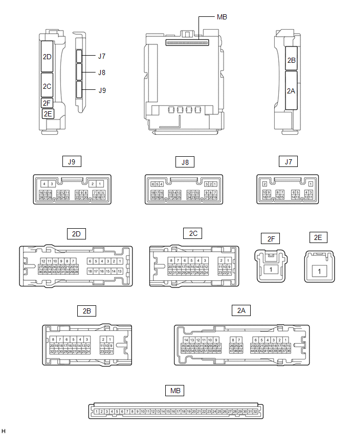
(a) Disconnect the MB main body ECU (multiplex network body ECU) connector.
Click here .gif)
(b) Measure the voltage and resistance according to the value(s) in the table below.
| Terminal No. (Symbol) | Wiring Color | Terminal Description | Condition | Specified Condition |
|---|---|---|---|---|
| MB-31 (BECU) - Body ground | - | Battery power supply | Always | 11 to 14 V |
| MB-32 (IG) - Body ground | - | IG power supply | Engine switch off | Below 1 V |
| Engine switch on (IG) | 11 to 14 V | |||
| MB-11 (GND1) - Body ground | - | Ground | Always | Below 1 Ω |
(c) Reconnect the MB main body ECU (multiplex network body ECU) connector.
Click here
(d) Check for pulses according to the value(s) in the table below.
| Terminal No. (Symbol) | Wiring Color | Terminal Description | Condition | Specified Condition |
|---|---|---|---|---|
| J9-16 (SFTP) - Body ground | - | Driving condition signal | Any of the following conditions are met:
| 11 to 14 V |
| Engine switch is on (IG) and any of the following conditions are met:
| Below 1 V |
 Problem Symptoms Table
PROBLEM SYMPTOMS TABLE NOTICE: When the fold seat control ECU (RH/LH seat) is replaced , it is necessary to perform initialization. Click here HINT:
Use the table below to help determine the caus ...
 IG Signal Circuit
DESCRIPTION Based on the engine switch signal, each fold seat control ECU determines the driving condition of the vehicle and enables or disables the fold and return functions. WIRING DIAGRAM CAUTION ...
Other materials:
Lexus RX (RX 350L, RX450h) 2016-2026 Repair Manual > Starter: Disassembly
DISASSEMBLY PROCEDURE 1. REMOVE MAGNET STARTER SWITCH ASSEMBLY (a) Remove the nut and disconnect the field coil lead wire from terminal C. (b) While holding the magnet starter switch assembly to the starter drive housing assembly, remove the 2 nuts. (c) Remove the magne ...
Lexus RX (RX 350L, RX450h) 2016-2026 Repair Manual > Cooling Fan System: Parts Location
PARTS LOCATION ILLUSTRATION *A for Cooling Fan Motor 200 W + 200 W Type - - *1 COOLING FAN ECU *2 COOLING FAN MOTOR LH *3 COOLING FAN MOTOR RH *4 FAN RELAY *5 NO. 1 ENGINE ROOM RELAY BLOCK AND NO. 1 JUNCTION BLOCK ASSEMBLY *6 ECM ILLUSTRATION *A for C ...
Lexus RX (RX 350L, RX450h) 2016-{YEAR} Owners Manual
- For your information
- Pictorial index
- For safety and security
- Instrument cluster
- Operation of each component
- Driving
- Lexus Display Audio system
- Interior features
- Maintenance and care
- When trouble arises
- Vehicle specifications
- For owners
Lexus RX (RX 350L, RX450h) 2016-{YEAR} Repair Manual

0.0132