Lexus RX (RX 350L, RX450h) 2016-2026 Repair Manual: IG Signal Circuit
DESCRIPTION
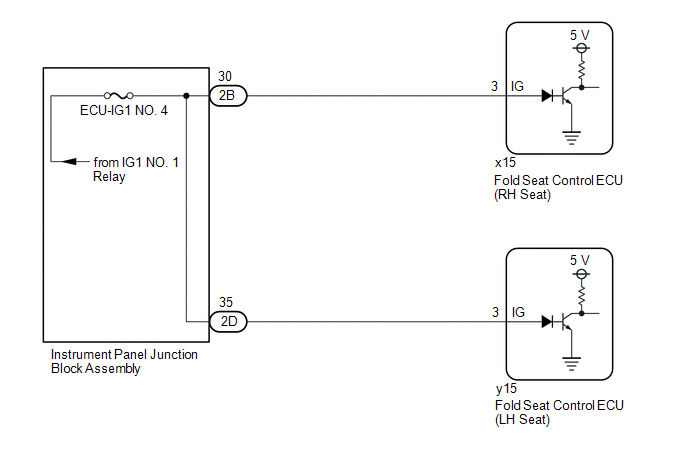
Based on the engine switch signal, each fold seat control ECU determines the driving condition of the vehicle and enables or disables the fold and return functions.
WIRING DIAGRAM
CAUTION / NOTICE / HINT
NOTICE:
- Inspect the fuses for circuits related to this system before performing the following procedure.
-
When the fold seat control ECU (RH/LH seat) is replaced, it is necessary to perform initialization.
Click here
.gif)
PROCEDURE
| 1. | CHECK REAR POWER SEAT CONTROL SYSTEM (for Third Row) |
(a) Check that the rear power seat control system (for Third Row) function operates normally.
| Result | Proceed to |
|---|---|
| Fold/Return functions of both rear No.2 power seats do not operate normally. | A |
| Fold/Return functions of rear No. 2 power seat RH do not operate normally. | B |
| Fold/Return functions of rear No. 2 power seat LH do not operate normally. | C |
| B | .gif) | GO TO STEP 4 |
| C | | GO TO STEP 6 |
|
.gif)
| 2. | CHECK HARNESS AND CONNECTOR (IG POWER SOURCE) |
| (a) Disconnect the x15 fold seat control ECU (RH Seat) connector. |
|
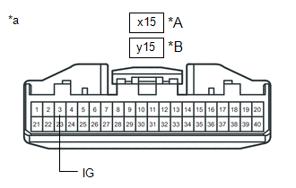
(b) Disconnect the y15 fold seat control ECU (LH seat) connector.
(c) Measure the voltage according to the value(s) in the table below.
Standard Voltage:
| Tester Connection | Condition | Specified Condition |
|---|---|---|
| x15-3 (IG) - Body ground | Engine switch off | Below 1 V |
| Engine switch on (IG) | 11 to 14 V | |
| y15-3 (IG) - Body ground | Engine switch off | Below 1 V |
| Engine switch on (IG) | 11 to 14 V |
| OK | | PROCEED TO NEXT SUSPECTED AREA SHOWN IN PROBLEM SYMPTOMS TABLE |
|
| 3. | CHECK HARNESS AND CONNECTOR (INSTRUMENT PANEL JUNCTION BLOCK ASSEMBLY - FOLD SEAT CONTROL ECU (RH/LH SEAT)) |
(a) Disconnect the 2B and 2D instrument panel junction block assembly connectors.
(b) Measure the resistance according to the value(s) in the table below.
Standard Resistance:
| Tester Connection | Condition | Specified Condition |
|---|---|---|
| 2B-30 or x15-3 (IG) - Body ground | Always | 10 kΩ or higher |
| 2D-35 or y15-3 (IG) - Body ground | Always | 10 kΩ or higher |
| OK | | REPLACE INSTRUMENT PANEL JUNCTION BLOCK ASSEMBLY |
| NG | | REPAIR OR REPLACE HARNESS OR CONNECTOR |
| 4. | INSPECT INSTRUMENT PANEL JUNCTION BLOCK ASSEMBLY |
(a) Measure the voltage according to the value(s) in the table below.
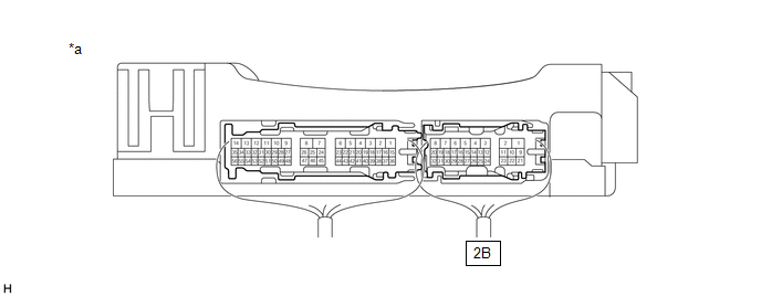
| *a | Component with harness connected (Instrument Panel Junction Block Assembly) | - | - |
Standard Voltage:
| Tester Connection | Condition | Specified Condition |
|---|---|---|
| 2B-30 - Body ground | Engine switch off | Below 1 V |
| Engine switch on (IG) | 11 to 14 V |
| NG | | REPLACE INSTRUMENT PANEL JUNCTION BLOCK ASSEMBLY |
|
| 5. | CHECK HARNESS AND CONNECTOR (INSTRUMENT PANEL JUNCTION BLOCK ASSEMBLY - FOLD SEAT CONTROL ECU (RH SEAT)) |
(a) Disconnect the x15 fold seat control ECU (RH seat) connector.
(b) Disconnect the 2B instrument panel junction block assembly connector.
(c) Measure the resistance according to the value(s) in the table below.
Standard Resistance:
| Tester Connection | Condition | Specified Condition |
|---|---|---|
| 2B-30 - x15-3 (IG) | Always | Below 1 Ω |
| OK | | PROCEED TO NEXT SUSPECTED AREA SHOWN IN PROBLEM SYMPTOMS TABLE |
| NG | | REPAIR OR REPLACE HARNESS OR CONNECTOR |
| 6. | INSPECT INSTRUMENT PANEL JUNCTION BLOCK ASSEMBLY |
(a) Measure the voltage according to the value(s) in the table below.
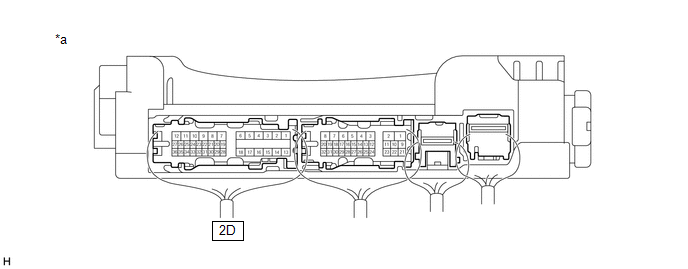
| *a | Component with harness connected (Instrument Panel Junction Block Assembly) | - | - |
Standard Voltage:
| Tester Connection | Condition | Specified Condition |
|---|---|---|
| 2D-35 - Body ground | Engine switch off | Below 1 V |
| Engine switch on (IG) | 11 to 14 V |
| NG | | REPLACE INSTRUMENT PANEL JUNCTION BLOCK ASSEMBLY |
|
| 7. | CHECK HARNESS AND CONNECTOR (INSTRUMENT PANEL JUNCTION BLOCK ASSEMBLY - FOLD SEAT CONTROL ECU (LH SEAT)) |
(a) Disconnect the y15 fold seat control ECU (LH seat) connector.
(b) Disconnect the 2D instrument panel junction block assembly connector.
(c) Measure the resistance according to the value(s) in the table below.
Standard Resistance:
| Tester Connection | Condition | Specified Condition |
|---|---|---|
| 2D-35 - y15-3 (IG) | Always | Below 1 Ω |
| OK | | PROCEED TO NEXT SUSPECTED AREA SHOWN IN PROBLEM SYMPTOMS TABLE |
| NG | | REPAIR OR REPLACE HARNESS OR CONNECTOR |
 Terminals Of Ecu
TERMINALS OF ECU CHECK FOLD SEAT CONTROL ECU (RH SEAT) (a) Disconnect the x15 and x16 fold seat control ECU (RH seat) connectors. (b) Measure the resistance and voltage according to the value(s) in t ...
 Park / Neutral Position Switch Circuit
DESCRIPTION Each fold seat control ECU receives the driving condition signal and engine switch signal from the main body ECU (multiplex network body ECU) to determine the driving state of the vehicle ...
Other materials:
Lexus RX (RX 350L, RX450h) 2016-2026 Repair Manual > Rear Bumper (w/o Rear No. 2 Seat): Removal
REMOVAL CAUTION / NOTICE / HINT The necessary procedures (adjustment, calibration, initialization, or registration) that must be performed after parts are removed and installed, or replaced during rear bumper assembly removal/installation are shown below. Necessary Procedures After Parts Removed/Ins ...
Lexus RX (RX 350L, RX450h) 2016-2026 Repair Manual > Audio And Visual System (for 12.3 Inch Display): Customize Parameters
CUSTOMIZE PARAMETERS CUSTOMIZING WITH REMOTE TOUCH (REMOTE OPERATION CONTROLLER ASSEMBLY) (a) Customizing with the touch function cancellation function. NOTICE: Confirm the touchpad surface is free of foreign matter before customizing. (1) Turn the engine switch on (ACC). (2) Simultaneously press an ...
Lexus RX (RX 350L, RX450h) 2016-{YEAR} Owners Manual
- For your information
- Pictorial index
- For safety and security
- Instrument cluster
- Operation of each component
- Driving
- Lexus Display Audio system
- Interior features
- Maintenance and care
- When trouble arises
- Vehicle specifications
- For owners
Lexus RX (RX 350L, RX450h) 2016-{YEAR} Repair Manual

0.01