Lexus RX (RX 350L, RX450h) 2016-2026 Repair Manual: Park / Neutral Position Switch Circuit
DESCRIPTION
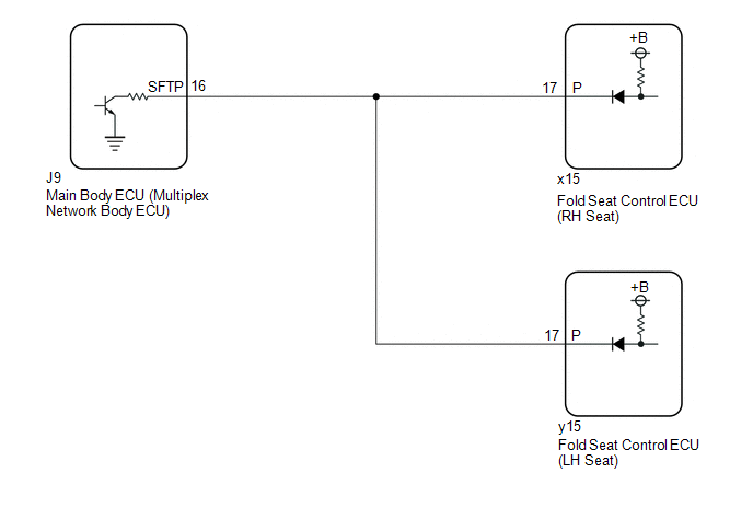
Each fold seat control ECU receives the driving condition signal and engine switch signal from the main body ECU (multiplex network body ECU) to determine the driving state of the vehicle and enable or disable the fold and return functions.
WIRING DIAGRAM
CAUTION / NOTICE / HINT
NOTICE:
- Before replacing the main body ECU (multiplex network body ECU), refer to registration.
-
When a fold seat control ECU (RH/LH seat) is replaced, it is necessary to perform initialization.
Click here
.gif)
PROCEDURE
| 1. | CHECK REAR POWER SEAT CONTROL SYSTEM (for Third Row) |
(a) Check that the rear power seat control system (for Third Row) function operates normally.
| Result | Proceed to |
|---|---|
| Fold/Return functions of both rear No. 2 power seats do not operate normally. | A |
| Fold/Return functions of rear No. 2 power seat RH do not operate normally. | B |
| Fold/Return functions of rear No. 2 power seat LH do not operate normally. | C |
| B | .gif) | GO TO STEP 4 |
| C | | GO TO STEP 6 |
|
.gif)
| 2. | CHECK HARNESS AND CONNECTOR (FOLD SEAT CONTROL ECU (RH/LH SEAT) - MAIN BODY ECU (MULTIPLEX NETWORK BODY ECU)) |
(a) Disconnect the x15 fold seat control ECU (RH seat) connector.
(b) Disconnect the y15 fold seat control ECU (LH seat) connector.
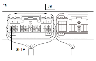
(c) Disconnect the J9 main body ECU (multiplex network body ECU) connector.
(d) Measure the resistance according to the value(s) in the table below.
Standard Resistance:
| Tester Connection | Condition | Specified Condition |
|---|---|---|
| x15-17 (P) or y15-17 (P) - J9-16 (SFTP) | Always | Below 1 Ω |
| x15-17 (P), y15-17 (P) or J9-16 (SFTP) - Body ground | Always | 10 kΩ or higher |
| NG | | REPAIR OR REPLACE HARNESS OR CONNECTOR |
|
| 3. | CHECK MAIN BODY ECU (MULTIPLEX NETWORK BODY ECU) |
(a) Reconnect the x15 fold seat control ECU (RH seat) connector.
(b) Reconnect the y15 fold seat control ECU (LH seat) connector.
(c) Reconnect the J9 main body ECU (multiplex network body ECU) connector.
| (d) Measure the voltage according to the value(s) in the table below. Standard Voltage:
|
|
| OK | | PROCEED TO NEXT SUSPECTED AREA SHOWN IN PROBLEM SYMPTOMS TABLE |
| NG | | REPLACE MAIN BODY ECU (MULTIPLEX NETWORK BODY ECU) |
| 4. | CHECK FOLD SEAT CONTROL ECU (RH SEAT) |
(a) Disconnect the y15 fold seat control ECU (LH seat) connector.
(b) Disconnect the J9 main body ECU (multiplex network body ECU) connector.
(c) Measure the voltage according to the value(s) in the table below.
Standard Voltage:
| Tester Connection | Condition | Specified Condition |
|---|---|---|
| J9-16 (SFTP) - Body ground | Always | 11 to 14 V |
| OK | | PROCEED TO NEXT SUSPECTED AREA SHOWN IN PROBLEM SYMPTOMS TABLE |
|
| 5. | CHECK HARNESS AND CONNECTOR (FOLD SEAT CONTROL ECU (RH SEAT) - MAIN BODY ECU (MULTIPLEX NETWORK BODY ECU)) |
(a) Disconnect the x15 fold seat control ECU (RH seat) connector.
(b) Measure the resistance according to the value(s) in the table below.
Standard Resistance:
| Tester Connection | Condition | Specified Condition |
|---|---|---|
| x15-17 (P) - J9-16 (SFTP) | Always | Below 1 Ω |
| OK | | REPLACE FOLD SEAT CONTROL ECU (RH SEAT) |
| NG | | REPAIR OR REPLACE HARNESS OR CONNECTOR |
| 6. | CHECK FOLD SEAT CONTROL ECU (LH SEAT) |
(a) Disconnect the x15 fold seat control ECU (RH seat) connector.
(b) Disconnect the J9 main body ECU (multiplex network body ECU) connector.
(c) Measure the voltage according to the value(s) in the table below.
Standard Voltage:
| Tester Connection | Condition | Specified Condition |
|---|---|---|
| J9-16 (SFTP) - Body ground | Always | 11 to 14 V |
| OK | | PROCEED TO NEXT SUSPECTED AREA SHOWN IN PROBLEM SYMPTOMS TABLE |
|
| 7. | CHECK HARNESS AND CONNECTOR (FOLD SEAT CONTROL ECU (LH SEAT) - MAIN BODY ECU (MULTIPLEX NETWORK BODY ECU)) |
(a) Disconnect the y15 fold seat control ECU (LH seat) connector.
(b) Measure the resistance according to the value(s) in the table below.
Standard Resistance:
| Tester Connection | Condition | Specified Condition |
|---|---|---|
| y15-17 (P) - J9-16 (SFTP) | Always | Below 1 Ω |
| OK | | REPLACE FOLD SEAT CONTROL ECU (LH SEAT) |
| NG | | REPAIR OR REPLACE HARNESS OR CONNECTOR |
 IG Signal Circuit
DESCRIPTION Based on the engine switch signal, each fold seat control ECU determines the driving condition of the vehicle and enables or disables the fold and return functions. WIRING DIAGRAM CAUTION ...
 Back Door Courtesy Switch Circuit
DESCRIPTION Each fold seat control ECU receives back door courtesy light switch input signal to determine the state of the back door and enable or disable the fold and return functions. WIRING DIAGRAM ...
Other materials:
Lexus RX (RX 350L, RX450h) 2016-2026 Owners Manual > Driving procedures: Hybrid transmission
Shifting the shift lever
While the power
switch is in ON mode, move the shift lever with the brake
pedal depressed.
When shifting the shift lever between P and D, make sure that the vehicle is
completely
stopped.
Shift position purpose
*1: To improve fuel efficiency and reduce noise ...
Lexus RX (RX 350L, RX450h) 2016-2026 Repair Manual > Charging System: Lost Communication with Alternator Missing Message (P161A87)
DESCRIPTION The ECM communicates with the generator assembly via LIN communication. If a LIN communication error is detected, the ECM stores this DTC. DTC No. Detection Item DTC Detection Condition Trouble Area Warning Indicate Memory Note P161A87 Lost Communication with Alterna ...
Lexus RX (RX 350L, RX450h) 2016-{YEAR} Owners Manual
- For your information
- Pictorial index
- For safety and security
- Instrument cluster
- Operation of each component
- Driving
- Lexus Display Audio system
- Interior features
- Maintenance and care
- When trouble arises
- Vehicle specifications
- For owners
Lexus RX (RX 350L, RX450h) 2016-{YEAR} Repair Manual

0.0103