Lexus RX (RX 350L, RX450h) 2016-2026 Repair Manual: Components
COMPONENTS
ILLUSTRATION
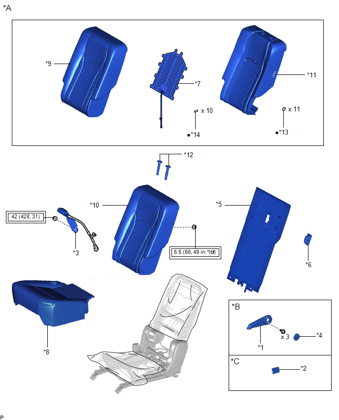
| *A | w/o Rear No. 2 Seat | *B | for Manual Seat |
| *C | for Power Seat | - | - |
| *1 | NO. 1 RECLINING ADJUSTER RELEASE HANDLE LH | *2 | POWER SEAT SWITCH ASSEMBLY |
| *3 | REAR CENTER SEAT INNER BELT ASSEMBLY | *4 | REAR SEAT COVER CAP LH |
| *5 | REAR SEATBACK BOARD CARPET ASSEMBLY LH | *6 | REAR SEATBACK COVER LH |
| *7 | SEAT HEATER ASSEMBLY | *8 | SEPARATE TYPE REAR SEAT CUSHION COVER WITH PAD |
| *9 | SEPARATE TYPE REAR SEATBACK COVER | *10 | SEPARATE TYPE REAR SEATBACK COVER WITH PAD |
| *11 | SEPARATE TYPE REAR SEATBACK PAD | *12 | REAR NO. 1 SEAT HEADREST SUPPORT |
| *13 | HOG RING | *14 | TAG PIN |
.png) | Tightening torque for "Major areas involving basic vehicle performance such as moving/turning/stopping": N*m (kgf*cm, ft.*lbf) | ● | Non-reusable part |
ILLUSTRATION
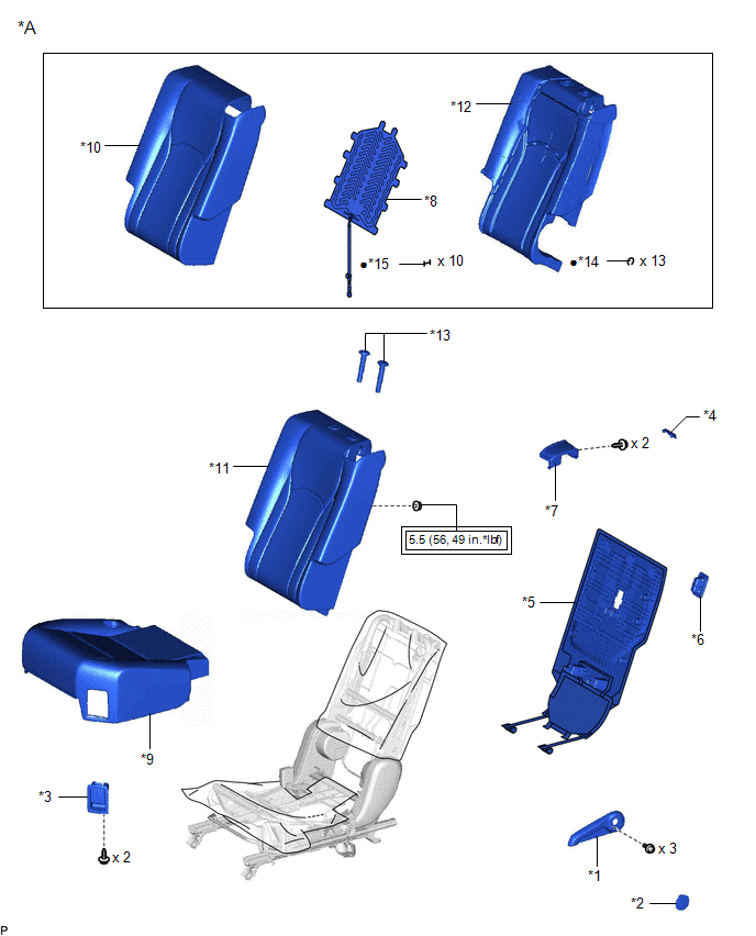
| *A | w/ Rear No. 2 Seat | - | - |
| *1 | NO. 1 RECLINING ADJUSTER RELEASE HANDLE LH | *2 | REAR SEAT COVER CAP LH |
| *3 | REAR SEAT LOCK CONTROL LEVER SUB-ASSEMBLY LH | *4 | REAR SEAT UPPER RECLINING COVER LH |
| *5 | REAR SEATBACK BOARD CARPET ASSEMBLY LH | *6 | REAR SEATBACK COVER LH |
| *7 | RECLINING REMOTE CONTROL LEVER SUB-ASSEMBLY LH | *8 | SEAT HEATER ASSEMBLY |
| *9 | SEPARATE TYPE REAR SEAT CUSHION COVER WITH PAD | *10 | SEPARATE TYPE REAR SEATBACK COVER |
| *11 | SEPARATE TYPE REAR SEATBACK COVER WITH PAD | *12 | SEPARATE TYPE REAR SEATBACK PAD |
| *13 | REAR NO. 1 SEAT HEADREST SUPPORT ASSEMBLY | *14 | HOG RING |
| *15 | TAG PIN | - | - |
| | Tightening torque for "Major areas involving basic vehicle performance such as moving/turning/stopping": N*m (kgf*cm, ft.*lbf) | ● | Non-reusable part |

 Inspection
INSPECTION PROCEDURE 1. INSPECT SEAT HEATER ASSEMBLY (a) Measure the resistance according to the value(s) in the table below. Standard Resistance: Tester Connection Condition Specified Cond ...
Other materials:
Lexus RX (RX 350L, RX450h) 2016-2026 Repair Manual > Automatic Transaxle Unit: Components
COMPONENTS ILLUSTRATION *1 TRANSMISSION CONTROL SHAFT LEVER *2 PARK/NEUTRAL POSITION SWITCH ASSEMBLY *3 LOCK NUT *4 LOCK PLATE *5 TRANSMISSION CASE PLUG ASSEMBLY *6 NO. 1 BREATHER PLUG (ATM) *7 TRANSMISSION BREATHER CLAMP *8 BREATHER PLUG HOSE *9 BREATHE ...
Lexus RX (RX 350L, RX450h) 2016-2026 Repair Manual > Vehicle Stability Control System: Right Rear Wheel Speed Sensor Circuit Intermittent (C05121F)
DESCRIPTION The speed sensor detects wheel speed and sends the appropriate signals to the skid control ECU (brake actuator assembly). These signals are used for brake control. Speed sensor rotors have rows of alternating N and S magnetic poles, and their magnetic fields change when the rotors turn. ...
Lexus RX (RX 350L, RX450h) 2016-{YEAR} Owners Manual
- For your information
- Pictorial index
- For safety and security
- Instrument cluster
- Operation of each component
- Driving
- Lexus Display Audio system
- Interior features
- Maintenance and care
- When trouble arises
- Vehicle specifications
- For owners
Lexus RX (RX 350L, RX450h) 2016-{YEAR} Repair Manual

0.0119