
Lexus RX (RX 350L, RX450h) 2016-2026 Repair Manual: Removal
REMOVAL
CAUTION / NOTICE / HINT
The necessary procedures (adjustment, calibration, initialization or registration) that must be performed after parts are removed and installed, or replaced during front seat inner belt assembly removal/installation are shown below.
Necessary Procedure After Parts Removed/Installed/Replaced| Replaced Part or Performed Procedure | Necessary Procedure | Effect/Inoperative Function when Necessary Procedure not Performed | Link |
|---|---|---|---|
| Disconnect cable from negative battery terminal | Memorize steering angle neutral point | Lane Control System | |
| Pre-collision system | |||
| Intelligent clearance sonar system*1 | |||
| Lighting system (w/ Automatic Headlight Beam Level Control System) | | ||
| Parking assist monitor system | | ||
| Panoramic view monitor system | | ||
| Initialize back door lock | Power door lock control system | | |
| Reset back door close position | Power Back Door System (w/ Outside Door Control Switch) | |
*1: When performing learning using the Techstream.
Click here .gif)
CAUTION:
-
Some of these service operations affect the SRS airbag system. Read the precautionary notices concerning the SRS airbag system before servicing.
Click here
- Wear protective gloves. Sharp areas on the parts may injure your hands.
.png)
HINT:
- Use the same procedure for the RH side and LH side.
- The following procedure is for the LH side.
NOTICE:
After the engine switch is turned off, the radio receiver assembly records various types of memory and settings. As a result, after turning the engine switch off, make sure to wait at least 120 seconds before disconnecting the cable from the negative (-) battery terminal.
PROCEDURE
1. REMOVE FRONT SEAT ASSEMBLY
Click here
2. REMOVE FRONT SEAT INNER BELT ASSEMBLY LH (for Driver Side)
(a) Disconnect each connector under the front seat assembly.
(b) Disengage each clamp under the front seat assembly.
| (c) Disengage the clamp. |
|
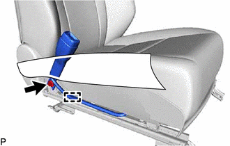
(d) Remove the nut and front seat inner belt assembly LH.
(e) Remove the front seat belt anchor plate as shown in the illustration.
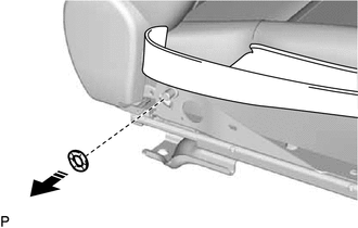
.png) | Remove in this Direction |
3. REMOVE FRONT SEAT INNER BELT ASSEMBLY RH (for Front Passenger Side)
(a) Disconnect each connector under the front seat assembly.
(b) Disengage each clamp under the front seat assembly.
| (c) Disengage the clamp. |
|
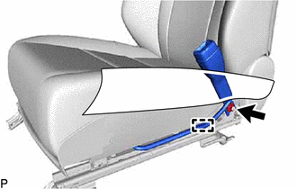
(d) Remove the nut and front seat inner belt assembly RH.
(e) Remove the front seat belt anchor plate as shown in the illustration.
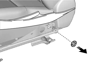
| | Remove in this Direction |
 Components
COMPONENTS ILLUSTRATION *A for Driver Side *B for Front Passenger Side *1 FRONT SEAT INNER BELT ASSEMBLY LH *2 FRONT SEAT INNER BELT ASSEMBLY RH *3 FRONT SEAT BELT ANCHOR PLA ...
 Inspection
INSPECTION PROCEDURE 1. INSPECT FRONT SEAT INNER BELT ASSEMBLY LH (a) Measure the resistance according to the value(s) in the table below. Standard Resistance: Tester Connection Condition S ...
Other materials:
Lexus RX (RX 350L, RX450h) 2016-2026 Repair Manual > Rear Power Outlet Socket (w/ Rear No. 2 Seat): Removal
REMOVAL PROCEDURE 1. REMOVE REAR NO. 2 SEAT ASSEMBLY Click here 2. REMOVE REAR DOOR SCUFF PLATE LH Click here 3. REMOVE REAR DOOR INSIDE SCUFF PLATE LH Click here 4. REMOVE REAR SEAT OUTER TRACK BRACKET COVER LH for 60/40 Split Seat Type: Click here for Captain Seat Type: Click here 5. ...
Lexus RX (RX 350L, RX450h) 2016-2026 Owners Manual > Lexus RX (RX 350L, RX450h) 2016-2026 Owners Manual: Maintenance
and care
Cleaning and protecting
the vehicle exterior
Perform the following to protect the vehicle and maintain it in prime
condition:
Working from top to bottom, liberally apply water to the vehicle body,
wheel
wells and underside of the vehicle to remove any dirt and dust.
Wash the vehicle b ...
Lexus RX (RX 350L, RX450h) 2016-{YEAR} Owners Manual
- For your information
- Pictorial index
- For safety and security
- Instrument cluster
- Operation of each component
- Driving
- Lexus Display Audio system
- Interior features
- Maintenance and care
- When trouble arises
- Vehicle specifications
- For owners
Lexus RX (RX 350L, RX450h) 2016-{YEAR} Repair Manual

0.0096