Lexus RX (RX 350L, RX450h) 2016-2026 Repair Manual: Disposal
DISPOSAL
CAUTION / NOTICE / HINT
CAUTION:
Before performing pre-disposal deployment of any SRS part, review and closely follow all applicable environmental and hazardous material regulations. Pre-disposal deployment may be considered hazardous material treatment.
PROCEDURE
1. PRECAUTION
CAUTION:
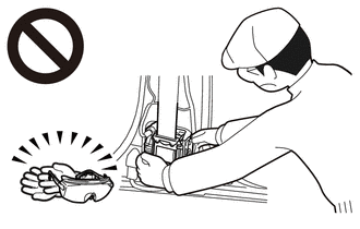
- Use gloves and safety glasses when handling a front seat outer belt assembly with a deployed pretensioner.
- Always wash your hands with water after completing the operation.
- Do not apply water, etc. to a front seat outer belt assembly with a deployed pretensioner.
- When deploying a seat belt pretensioner, always use the specified SST (SRS airbag deployment tool). Perform the operation in a place away from electrical noise.
- Never dispose of a front seat outer belt assembly with a pretensioner that has not been deployed.
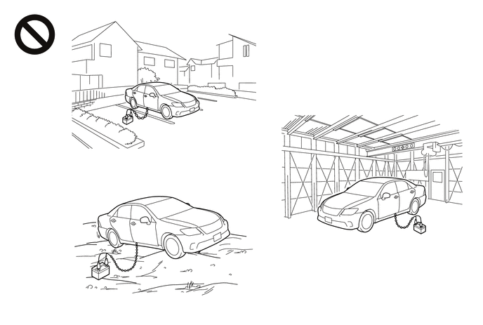
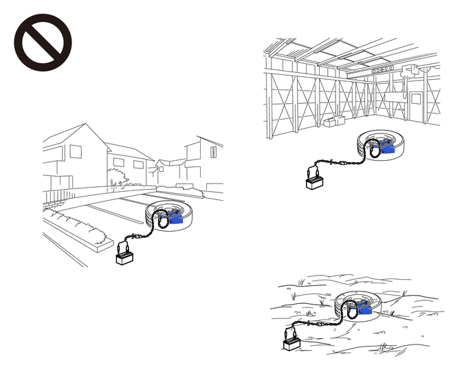
- The front seat outer belt assembly produces an exploding sound when the pretensioner is deployed, so perform the operation outdoors where it will not disturb nearby residents.
- When deploying a seat belt pretensioner, perform the operation at least 10 m (32.8 ft.) away from the vehicle.
HINT:
When scrapping a vehicle equipped with a seat belt pretensioner or disposing of a front seat outer belt assembly with a seat belt pretensioner, always deploy the seat belt pretensioner first in accordance with the procedure described below. If any abnormality occurs during deployment of the seat belt pretensioner, contact the SERVICE DEPARTMENT of the distributor.
2. DISPOSE OF FRONT SEAT OUTER BELT ASSEMBLY (When Installed to Vehicle)
NOTICE:
- When disposing of a front seat outer belt assembly with a pretensioner, never deploy the pretensioner in the customer's vehicle.
- Be sure to observe the following procedure when deploying a seat belt pretensioner.
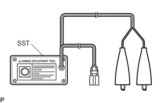
(a) Check the function of SST.
SST: 09082-00700
CAUTION:
When deploying a seat belt pretensioner, always use the specified SST.
| (1) Connect the red clip of SST to the positive (+) battery terminal and the black clip to the negative (-) battery terminal. HINT: At this time, do not connect the yellow connector. It will be connected to the seat belt pretensioner in a later step. |
|
| (2) Press the SST activation switch and check that the LED of the SST activation switch illuminates. CAUTION: If the LED is illuminated when the SST activation switch is not pressed, SST may be malfunctioning. In this case, do not use the malfunctioning SST. |
|
(b) Refer to Precaution.
Click here .gif)
(c) Disconnect the cable from the negative (-) battery terminal.
CAUTION:
Wait at least 90 seconds after disconnecting the cable from the negative (-) battery terminal to disable the SRS system.
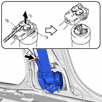
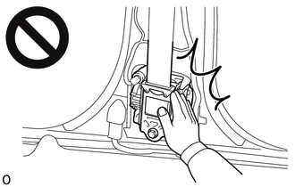
(d) Disconnect the seat belt pretensioner connector.
(1) Remove the lower center pillar garnish.
Click here
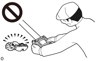
| (2) Using a screwdriver, pull out the locking button as shown in the illustration to release the lock and disconnect the pretensioner connector. HINT: Tape the screwdriver tip before use. |
|
(e) Connect SST.
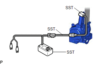
(1) After connecting the following SST to each other, connect them to the seat belt pretensioner.
SST: 09082-00700
SST: 09082-00802
09082-10801
09082-20801
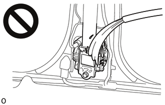
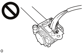
NOTICE:
To avoid damaging the SST connector or wire harness, do not lock the secondary lock of the pretensioner connector.
(2) Move SST at least 10 m (32.8 ft.) away from the front of the vehicle.
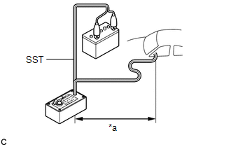
| *a | 10 m (32.8 ft.) or more |
CAUTION:
-
Do not perform deployment with any of the doors or windows open.
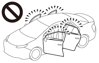
- If deployment is performed with any of the doors or windows open, dust and gas may enter the eyes or be breathed in.
(3) Close all of the doors and windows of the vehicle.
NOTICE:
Do not damage the SST wire harness.
(f) Deploy the seat belt pretensioner.
| (1) Check that no one is inside the vehicle or within a 10 m (32.8 ft.) radius of the vehicle. |
|
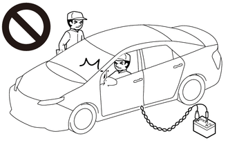
(2) Connect the red clip of SST to the battery positive (+) terminal and the black clip to the negative (-) terminal.
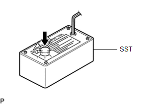
(3) Press the SST activation switch to deploy the seat belt pretensioner.
HINT:
The seat belt pretensioner will deploy at the same time as the LED of SST illuminates.
CAUTION:
-
The front seat outer belt assembly produces an exploding sound when the pretensioner is deployed, so perform the operation outdoors where it will not disturb nearby residents.
- If this procedure is performed indoors or on a rough road where safety cannot be ensured, unforeseen injuries may occur. Also, if this procedure is performed near a residential area, the deployment noise may disturb nearby residents.
(g) Dispose of the front seat outer belt assembly.
(1) Remove the front seat outer belt assembly and SST.
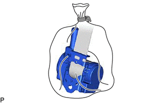
(2) Place the front seat outer belt assembly in a plastic bag, tie the end tightly, and dispose of it in the same way as other general parts.
CAUTION:
-
The front seat outer belt assembly becomes extremely hot when the pretensioner is deployed, so do not touch it for at least 30 minutes after deployment.
-
Do not apply water, etc. to a front seat outer belt assembly with a deployed pretensioner.
- If water is applied to the front seat outer belt assembly immediately after deployment, burns may be caused by the resulting steam.
-
Always wear safety glasses and gloves when handling a front seat outer belt assembly with a deployed pretensioner.
- If a front seat outer belt assembly with a deployed pretensioner is touched without wearing safety glasses and gloves, hot parts may cause burns and dust may enter the eyes.
- After removal, quickly seal the front seat outer belt assembly in a plastic bag.
-
Never dispose of a front seat outer belt assembly with a pretensioner that has not been deployed.
- If a front seat outer belt assembly with a pretensioner that has not been deployed is disposed of, and then deploys accidentally, unforeseen injuries may occur.
- Always wash your hands with water after completing the operation.
HINT:
When scrapping a vehicle, deploy the seat belt pretensioners, and then scrap the vehicle with the front seat outer belt assemblies installed.
3. DISPOSE OF FRONT SEAT OUTER BELT ASSEMBLY (When not Installed to Vehicle)
NOTICE:
- When disposing of a front seat outer belt assembly with a pretensioner, never deploy the pretensioner in the customer's vehicle.
- Be sure to observe the following procedure when deploying a seat belt pretensioner.
(a) Check the function of SST.
SST: 09082-00700
CAUTION:
When deploying a seat belt pretensioner, always use the specified SST.
| (1) Connect the red clip of SST to the positive (+) battery terminal and the black clip to the negative (-) battery terminal. HINT: At this time, do not connect the yellow connector. It will be connected to the seat belt pretensioner in a later step. |
|
| (2) Press the SST activation switch and check that the LED of the SST activation switch illuminates. CAUTION: If the LED is illuminated when the SST activation switch is not pressed, SST may be malfunctioning. In this case, do not use the malfunctioning SST. |
|
(b) Refer to Precaution.
Click here
(c) Remove the front seat outer belt assembly.
Click here
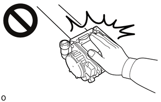
| (d) Wind the seat belt webbing with the retractor. |
|
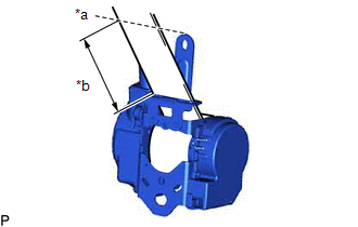
(e) When the seat belt webbing is sufficiently wound, cut the seat belt webbing approximately 100 mm (3.94 in.) from the retractor, as shown in the illustration.
HINT:
The retractor resistance increases in proportion with how much the seat belt webbing is wound.
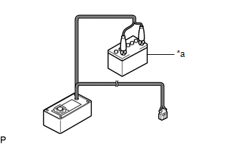
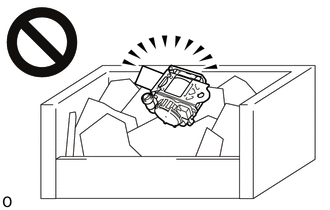
| (f) Connect SST. (1) After connecting the following SST to each other, connect them to the seat belt pretensioner. SST: 09082-00700 SST: 09082-00802 09082-10801 09082-20801 NOTICE: To avoid damaging the SST connector or wire harness, do not lock the secondary lock of the pretensioner connector. (2) Place the front seat outer belt assembly on the ground and cover it with an unneeded tire and wheel assembly. NOTICE:
(3) Position and hold SST at least 10 m (32.8 ft.) away from the tire and wheel assembly. NOTICE: Do not damage the SST wire harness. |
|
(g) Deploy the seat belt pretensioner.
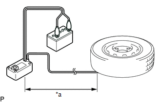
| *a | 10 m (32.8 ft.) or more |
(1) Check that no one is within a 10 m (32.8 ft.) radius of the tire and wheel assembly.
(2) Connect the red clip of SST to the positive (+) battery terminal and the black clip to the negative (-) battery terminal.
(3) Press the SST activation switch to deploy the seat belt pretensioner.
HINT:
The seat belt pretensioner will deploy at the same time as the LED of SST illuminates.
CAUTION:
-
The front seat outer belt assembly produces an exploding sound when the pretensioner is deployed, so perform the operation outdoors where it will not disturb nearby residents.
- If this procedure is performed indoors or on a rough road where safety cannot be ensured, unforeseen injuries may occur. Also, if this procedure is performed near a residential area, the deployment noise may disturb nearby residents.
(h) Dispose of the front seat outer belt assembly.
(1) Remove the tire and wheel assembly and SST.
(2) Place the front seat outer belt assembly in a plastic bag, tie the end tightly, and dispose of it in the same way as other general parts.
CAUTION:
-
The front seat outer belt assembly becomes extremely hot when the pretensioner is deployed, so do not touch it for at least 30 minutes after deployment.
-
Do not apply water, etc. to the front seat outer belt assembly with a deployed pretensioner.
- If water is applied to the front seat outer belt assembly immediately after deployment, burns may be caused by the resulting steam.
-
Always wear safety glasses and gloves when handling a front seat outer belt assembly with a deployed pretensioner.
- If a front seat outer belt assembly with a deployed pretensioner is touched without wearing safety glasses and gloves, hot parts may cause burns and dust may enter the eyes.
- After removal, quickly seal the front seat outer belt assembly in a plastic bag.
-
Never dispose of a front seat outer belt assembly with a pretensioner that has not been deployed.
- If a front seat outer belt assembly with a pretensioner that has not been deployed is disposed of, and then deploys accidentally, unforeseen injuries may occur.
- Always wash your hands with water after completing the operation
 Installation
INSTALLATION CAUTION / NOTICE / HINT HINT:
Use the same procedure for the RH side and LH side.
The following procedure is for the LH side.
PROCEDURE 1. INSTALL FRONT SHOULDER BELT ANCHOR ADJUS ...

Other materials:
Lexus RX (RX 350L, RX450h) 2016-2026 Repair Manual > Sfi System: Low Pressure Fuel System Pressure - Too High (P008B00)
DESCRIPTION Refer to DTC P008A00. Click here DTC No. Detection Item DTC Detection Condition Trouble Area MIL Memory Note P008B00 Low Pressure Fuel System Pressure - Too High Actual fuel pressure (for low pressure side) value higher than target fuel pressure (for low pressure ...
Lexus RX (RX 350L, RX450h) 2016-2026 Repair Manual > Rear Speed Sensor (for Awd): Installation
INSTALLATION CAUTION / NOTICE / HINT HINT: The rear speed sensor rotor is a component of the rear axle hub and bearing assembly. If the rear speed sensor rotor is malfunctioning, replace the rear axle hub and bearing assembly. PROCEDURE 1. INSTALL REAR SPEED SENSOR LH (w/o AVS) (a) Install the rear ...
Lexus RX (RX 350L, RX450h) 2016-{YEAR} Owners Manual
- For your information
- Pictorial index
- For safety and security
- Instrument cluster
- Operation of each component
- Driving
- Lexus Display Audio system
- Interior features
- Maintenance and care
- When trouble arises
- Vehicle specifications
- For owners
Lexus RX (RX 350L, RX450h) 2016-{YEAR} Repair Manual

0.0128