Lexus RX (RX 350L, RX450h) 2016-2026 Repair Manual: Installation
INSTALLATION
CAUTION / NOTICE / HINT
HINT:
The rear speed sensor rotor is a component of the rear axle hub and bearing assembly. If the rear speed sensor rotor is malfunctioning, replace the rear axle hub and bearing assembly.
PROCEDURE
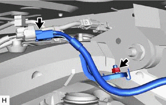
1. INSTALL REAR SPEED SENSOR LH (w/o AVS)
(a) Install the rear speed sensor LH and sensor clamp to the rear axle carrier sub-assembly LH and rear trailing arm assembly LH with the 2 bolts.
Torque:
8.5 N·m {87 kgf·cm, 75 in·lbf}
NOTICE:
- Keep the tip of the rear speed sensor LH and installation hole free of foreign matter.
- Firmly insert the rear speed sensor body into the rear axle carrier sub-assembly LH before tightening the bolt.
- After installing the rear speed sensor LH to the rear axle carrier sub-assembly LH, make sure that there is no clearance between the rear speed sensor stay and rear axle carrier sub-assembly LH. Also make sure that no foreign matter is stuck between the parts.
- Do not twist the rear speed sensor wire harness when installing it.
(b) Install the 2 sensor clamps to the rear upper control arm assembly LH with the 2 bolts.
Torque:
8.5 N·m {87 kgf·cm, 75 in·lbf}
NOTICE:
Do not twist the rear speed sensor wire harness when installing it.
| (c) Install the sensor clamp to the rear suspension member sub-assembly with the nut. Torque: 8.5 N·m {87 kgf·cm, 75 in·lbf} NOTICE: Do not twist the rear speed sensor wire harness when installing it. |
|
(d) Connect the rear speed sensor connector.
2. INSTALL REAR SPEED SENSOR LH (w/ AVS)
(a) Install the rear speed sensor LH and sensor clamp to the rear axle carrier sub-assembly LH and rear trailing arm assembly LH with the 2 bolts.
Torque:
8.5 N·m {87 kgf·cm, 75 in·lbf}
NOTICE:
- Keep the tip of the rear speed sensor LH and installation hole free of foreign matter.
- Firmly insert the rear speed sensor body into the rear axle carrier sub-assembly LH before tightening the bolt.
- After installing the rear speed sensor LH to the rear axle carrier sub-assembly LH, make sure that there is no clearance between the rear speed sensor stay and rear axle carrier sub-assembly LH. Also make sure that no foreign matter is stuck between the parts.
- Do not twist the rear speed sensor wire harness when installing it.
(b) Install the sensor clamp to the rear upper control arm assembly LH with the bolt.
Torque:
8.5 N·m {87 kgf·cm, 75 in·lbf}
NOTICE:
Do not twist the rear speed sensor wire harness when installing it.
(c) Connect the rear speed sensor connector.
3. INSTALL REAR SPEED SENSOR RH (w/o AVS)
(a) Install the rear speed sensor RH and sensor clamp to the rear axle carrier sub-assembly RH and rear trailing arm assembly RH with the 2 bolts.
Torque:
8.5 N·m {87 kgf·cm, 75 in·lbf}
NOTICE:
- Keep the tip of the rear speed sensor RH and installation hole free of foreign matter.
- Firmly insert the rear speed sensor body into the rear axle carrier sub-assembly RH before tightening the bolt.
- After installing the rear speed sensor RH to the rear axle carrier sub-assembly RH, make sure that there is no clearance between the rear speed sensor stay and rear axle carrier sub-assembly RH. Also make sure that no foreign matter is stuck between the parts.
- Do not twist the rear speed sensor wire harness when installing it.
(b) Install the 2 sensor clamps to the rear upper control arm assembly RH with the 2 bolts.
Torque:
8.5 N·m {87 kgf·cm, 75 in·lbf}
NOTICE:
Do not twist the rear speed sensor wire harness when installing it.
| (c) Install the sensor clamp to the rear suspension member sub-assembly with the nut. Torque: 8.5 N·m {87 kgf·cm, 75 in·lbf} NOTICE: Do not twist the rear speed sensor wire harness when installing it. |
|
(d) Connect the rear speed sensor connector.
(e) Engage the clamp to install the wire harness to the sensor clamp.
4. INSTALL REAR SPEED SENSOR RH (w/ AVS)
(a) Install the rear speed sensor RH and sensor clamp to the rear axle carrier sub-assembly RH and rear trailing arm assembly RH with the 2 bolts.
Torque:
8.5 N·m {87 kgf·cm, 75 in·lbf}
NOTICE:
- Keep the tip of the rear speed sensor RH and installation hole free of foreign matter.
- Firmly insert the rear speed sensor body into the rear axle carrier sub-assembly RH before tightening the bolt.
- After installing the rear speed sensor RH to the rear axle carrier sub-assembly RH, make sure that there is no clearance between the rear speed sensor stay and rear axle carrier sub-assembly RH. Also make sure that no foreign matter is stuck between the parts.
- Do not twist the rear speed sensor wire harness when installing it.
(b) Install the sensor clamp to the rear upper control arm assembly RH with the bolt.
Torque:
8.5 N·m {87 kgf·cm, 75 in·lbf}
NOTICE:
Do not twist the rear speed sensor wire harness when installing it.
(c) Connect the rear speed sensor connector.
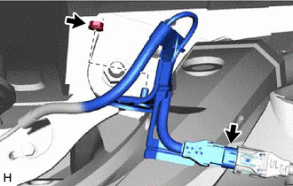
5. INSTALL NO. 2 PARKING BRAKE WIRE ASSEMBLY (for LH Side)
(a) Install the No. 2 parking brake wire assembly to the sensor clamp with the bolt.
Torque:
8.5 N·m {87 kgf·cm, 75 in·lbf}
(b) Install the No. 2 parking brake wire assembly to the rear axle carrier sub-assembly LH with the bolt.
Torque:
15 N·m {153 kgf·cm, 11 ft·lbf}
(c) Connect the connector.
6. INSTALL NO. 1 PARKING BRAKE WIRE ASSEMBLY (for RH Side)
HINT:
Use the same procedure for the No. 2 parking brake wire assembly.
7. INSTALL REAR WHEEL
Click here .gif)
8. CHECK FOR SPEED SENSOR SIGNAL
Click here
 Components
COMPONENTS ILLUSTRATION *A for LH Side w/o AVS - - *1 NO. 2 PARKING BRAKE WIRE ASSEMBLY *2 REAR SPEED SENSOR LH N*m (kgf*cm, ft.*lbf): Specified torque - - ILLUSTRATI ...
 Removal
REMOVAL CAUTION / NOTICE / HINT HINT: The rear speed sensor rotor is a component of the rear axle hub and bearing assembly. If the rear speed sensor rotor is malfunctioning, replace the rear axle hub ...
Other materials:
Lexus RX (RX 350L, RX450h) 2016-2026 Repair Manual > Generator (for 150 A Type): Installation
INSTALLATION PROCEDURE 1. INSTALL GENERATOR ASSEMBLY (a) Install the wire harness clamp bracket with the bolt. Torque: 8.4 N·m {86 kgf·cm, 74 in·lbf} (b) Type A: (1) Install the generator assembly with the 2 bolts. Torque: 43 N·m {438 kgf·cm, 32 ft·lbf} (2) Temporarily install the generator ...
Lexus RX (RX 350L, RX450h) 2016-2026 Repair Manual > Park / Neutral Position Switch: On-vehicle Inspection
ON-VEHICLE INSPECTION PROCEDURE 1. SECURE VEHICLE (a) Fully apply the parking brake and chock a wheel. CAUTION:
Make sure to apply the parking brake and chock a wheel before performing this procedure.
If the vehicle is not secure and the shift lever is moved to N, the vehicle may suddenly move, ...
Lexus RX (RX 350L, RX450h) 2016-{YEAR} Owners Manual
- For your information
- Pictorial index
- For safety and security
- Instrument cluster
- Operation of each component
- Driving
- Lexus Display Audio system
- Interior features
- Maintenance and care
- When trouble arises
- Vehicle specifications
- For owners
Lexus RX (RX 350L, RX450h) 2016-{YEAR} Repair Manual

0.0082