Lexus RX (RX 350L, RX450h) 2016-2026 Repair Manual: Installation
INSTALLATION
PROCEDURE
1. INSTALL REAR NO. 3 SPEAKER ASSEMBLY
NOTICE:
Do not touch the speaker cone.
| (a) Install the rear No. 3 speaker assembly with the 3 nuts. HINT: Install the nuts in the order shown in the illustration. Torque: 7.9 N·m {81 kgf·cm, 70 in·lbf} |
|

(b) Connect the connector.
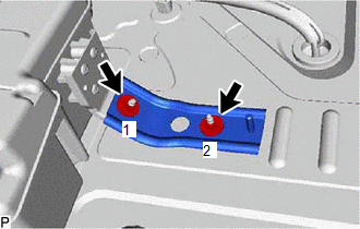
2. INSTALL REAR NO. 1 SPEAKER BRACKET
| (a) Install the rear No. 1 speaker bracket with the 2 nuts. HINT: Install the nuts in the order shown in the illustration. Torque: 7.9 N·m {81 kgf·cm, 70 in·lbf} |
|
3. INSTALL NO. 2 DECK BOARD REINFORCEMENT
(a) Install the rear No. 2 deck board reinforcement with the 2 bolts and nut.
Torque:
16.5 N·m {168 kgf·cm, 12 ft·lbf}
4. INSTALL FUEL PUMP CONTROL ECU ASSEMBLY
Click here .gif)
5. INSTALL DECK TRIM SIDE PANEL ASSEMBLY LH
Click here
6. INSTALL NO. 1 LUGGAGE COMPARTMENT LIGHT ASSEMBLY
Click here
7. INSTALL ROPE HOOK ASSEMBLY
Click here
8. INSTALL NO. 1 LUGGAGE COMPARTMENT TRIM HOOK
Click here
9. INSTALL REAR FLOOR FINISH SIDE PLATE LH
Click here
10. INSTALL REAR SEAT SIDE GARNISH LH
Click here
11. INSTALL UPPER QUARTER TRIM PAD LH
Click here
12. INSTALL REAR SEAT ASSEMBLY LH
Click here
13. INSTALL REAR DOOR SCUFF PLATE LH
Click here
14. INSTALL REAR FLOOR FINISH PLATE
Click here
15. INSTALL DECK SIDE TRIM BOX RH
Click here
16. INSTALL FRONT DECK FLOOR BOX
Click here
17. INSTALL REAR NO. 4 FLOOR BOARD
Click here
18. INSTALL REAR DECK FLOOR BOX
Click here
19. INSTALL REAR NO. 3 FLOOR BOARD
Click here
20. INSTALL DECK BOARD ASSEMBLY
Click here
21. INSTALL TONNEAU COVER ASSEMBLY
Click here
 Inspection
INSPECTION PROCEDURE 1. INSPECT REAR NO. 3 SPEAKER ASSEMBLY (a) With the speaker installed, check that there is no looseness or other abnormalities. (b) Check that there is no foreign matter in the sp ...

Other materials:
Lexus RX (RX 350L, RX450h) 2016-2026 Repair Manual > Sliding Roof Housing (for Panoramic Moon Roof): Reassembly
REASSEMBLY PROCEDURE 1. INSTALL REAR SLIDING ROOF GARNISH (a) Engage the 3 guides and 4 claws to install the rear sliding roof garnish to the sliding roof housing panel. 2. INSTALL NO. 1 SLIDING ROOF SIDE GARNISH LH (a) Clean the sliding roof housing panel. (1) Using a heat light, hea ...
Lexus RX (RX 350L, RX450h) 2016-2026 Repair Manual > Front Camera System: Parts Location
PARTS LOCATION ILLUSTRATION *1 FORWARD RECOGNITION CAMERA *2 FORWARD RECOGNITION WITH HEATER HOOD SUB-ASSEMBLY *3 SKID CONTROL ECU (BRAKE ACTUATOR ASSEMBLY) *4 ECM ILLUSTRATION *A for TFT Meter Type *B for Optitron Meter Type *1 STEERING VIBRATION ECU *2 SP ...
Lexus RX (RX 350L, RX450h) 2016-{YEAR} Owners Manual
- For your information
- Pictorial index
- For safety and security
- Instrument cluster
- Operation of each component
- Driving
- Lexus Display Audio system
- Interior features
- Maintenance and care
- When trouble arises
- Vehicle specifications
- For owners
Lexus RX (RX 350L, RX450h) 2016-{YEAR} Repair Manual

0.0093