
Lexus RX (RX 350L, RX450h) 2016-2026 Repair Manual: Seat Belt Tension Reducer System
Parts Location
PARTS LOCATION
ILLUSTRATION
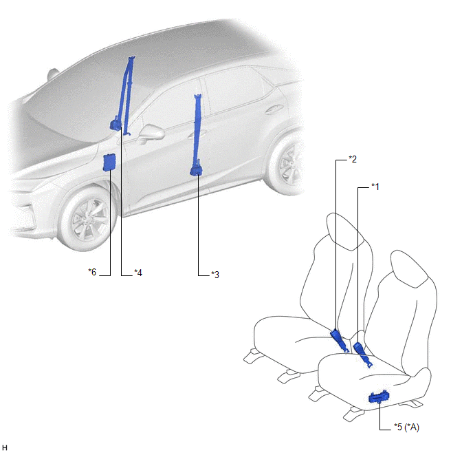
| *A | w/ Seat Position Memory System | - | - |
| *1 | FRONT SEAT INNER BELT ASSEMBLY LH | *2 | FRONT SEAT INNER BELT ASSEMBLY RH |
| *3 | FRONT SEAT OUTER BELT ASSEMBLY LH | *4 | FRONT SEAT OUTER BELT ASSEMBLY RH |
| *5 | POSITION CONTROL ECU AND SWITCH ASSEMBLY LH | *6 | INSTRUMENT PANEL JUNCTION BLOCK ASSEMBLY - ECU-IG1 NO. 4 FUSE |
Precaution
PRECAUTION
PRECAUTION FOR DISCONNECTING CABLE FROM NEGATIVE BATTERY TERMINAL
NOTICE:
When disconnecting the cable from the negative (-) battery terminal, initialize the following systems after the cable is reconnected.
| System Name | See Procedure |
|---|---|
| Lane Control System | |
| Pre-collision System | |
| Intelligent Clearance Sonar System | |
| Parking Assist Monitor System | |
| Panoramic View Monitor System | |
| Lighting System (w/ Automatic Headlight Beam Level Control System) | |
| Power Door Lock Control System | |
| Power Back Door System (w/ Outside Door Control Switch) |
.gif)
System Diagram
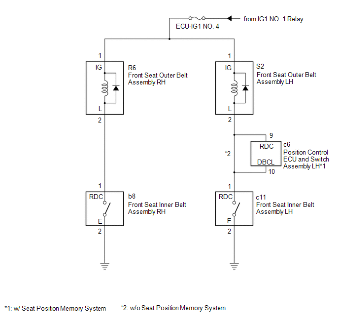
SYSTEM DIAGRAM
Problem Symptoms Table
PROBLEM SYMPTOMS TABLE
HINT:
- Use the table below to help determine the cause of problem symptoms. If multiple suspected areas are listed, the potential causes of the symptoms are listed in order of probability in the "Suspected Area" column of the table. Check each symptom by checking the suspected areas in the order they are listed. Replace parts as necessary.
- Inspect the fuses and relays related to this system before inspecting the suspected areas below.
| Symptom | Suspected Area | Link |
|---|---|---|
| Driver seat belt tension reducer does not operate | Wire harness or connector | - |
| Front seat inner belt assembly LH | | |
| Front seat outer belt assembly LH | | |
| Position control ECU and switch assembly LH* | - | |
| Front passenger seat belt tension reducer does not operate | Wire harness or connector | - |
| Front seat inner belt assembly RH | | |
| Front seat outer belt assembly RH | |
.gif)
- *: w/ Seat Position Memory System
 Installation
INSTALLATION CAUTION / NOTICE / HINT HINT:
Use the same procedure for the RH side and LH side.
The following procedure is for the LH side.
PROCEDURE 1. INSTALL OUTER BELT ANCHOR BRACKET SUB-AS ...

Other materials:
Lexus RX (RX 350L, RX450h) 2016-2026 Repair Manual > Can Communication System: Check Bus 5 Line for Short to GND
DESCRIPTION There may be a short circuit between one of the CAN bus lines and GND when there is no resistance between terminal 15 (CA5H) of the network gateway ECU and terminal 4 (CG) of the DLC3, or terminal 16 (CA5L) of the network gateway ECU and terminal 4 (CG) of the DLC3. Symptom Trouble ...
Lexus RX (RX 350L, RX450h) 2016-2026 Repair Manual > 2gr-fks (starting): Relay
On-vehicle InspectionON-VEHICLE INSPECTION PROCEDURE 1. INSPECT ST RELAY (a) Check the resistance. (1) Measure the resistance according to the value(s) in the table below. Standard Resistance: Tester Connection Condition Specified Condition 3 - 5 Battery voltage not applied to termi ...
Lexus RX (RX 350L, RX450h) 2016-{YEAR} Owners Manual
- For your information
- Pictorial index
- For safety and security
- Instrument cluster
- Operation of each component
- Driving
- Lexus Display Audio system
- Interior features
- Maintenance and care
- When trouble arises
- Vehicle specifications
- For owners
Lexus RX (RX 350L, RX450h) 2016-{YEAR} Repair Manual

0.012