Lexus RX (RX 350L, RX450h) 2016-2026 Repair Manual: Rear Seat Belt Warning Light Malfunction
DESCRIPTION
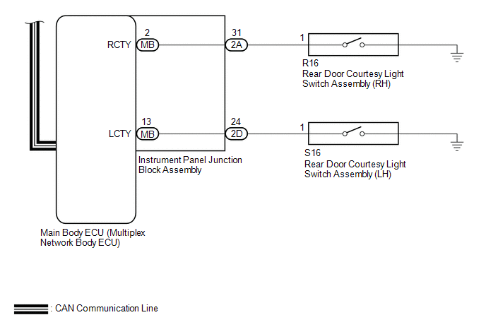
The main body ECU (multiplex network body ECU) detects whether either rear door is open or closed based on the condition of the left and right courtesy light switches and then sends the rear door status signal to the combination meter assembly. The combination meter assembly detects the rear seat belt state. The rear seat belt warning lights on the radio receiver assembly illuminate or turn off in accordance with the rear door state, vehicle speed and rear seat belt state.
WIRING DIAGRAM

CAUTION / NOTICE / HINT
NOTICE:
-
The seat belt warning system uses the CAN communication system. First, confirm that there are no malfunctions in the CAN communication system. Refer to the How to Proceed with Troubleshooting procedure.
Click here
.gif)
- Inspect the fuses for circuits related to this system before performing the following procedure.
PROCEDURE
| 1. | READ VALUE USING TECHSTREAM |
(a) Connect the Techstream to the DLC3.
(b) Turn the engine switch on (IG).
(c) Turn the Techstream on.
(d) Enter the following menus: Body Electrical / Main Body / Data List.
(e) Read the Data List according to the display on the Techstream.
Body Electrical > Main Body > Data List| Tester Display | Measurement Item | Range | Normal Condition | Diagnostic Note |
|---|---|---|---|---|
| RR Door Courtesy SW | Rear door courtesy light switch RH | ON or OFF | ON: Rear door RH open OFF: Rear door RH closed | - |
| RL Door Courtesy SW | Rear door courtesy light switch LH | ON or OFF | ON: Rear door LH open OFF: Rear door LH closed | - |
| Tester Display |
|---|
| RR Door Courtesy SW |
| RL Door Courtesy SW |
OK:
The Techstream display changes correctly in response to the rear door condition.
| NG | .gif) | GO TO LIGHTING SYSTEM |
|
.gif)
| 2. | CHECK REAR SEAT BELT WARNING |
| (a) Check the rear seat belt warning function. Click here
|
|
.png)
| A | | USE SIMULATION METHOD TO CHECK |
| C | | GO TO STEP 7 |
| D | | GO TO STEP 12 |
| E | | GO TO STEP 18 |
| F | | GO TO STEP 23 |
| G | | GO TO STEP 28 |
| H | | GO TO STEP 33 |
| I | | GO TO STEP 38 |
| J | | GO TO STEP 43 |
|
| 3. | CHECK HARNESS AND CONNECTOR (IG POWER SUPPLY - RADIO RECEIVER ASSEMBLY) |
(a) Disconnect the J151*1 or J147*2 radio receiver assembly connector.
- *1: w/ 12.3 Inch Display
- *2: w/o 12.3 Inch Display
(b) Measure the voltage according to the value(s) in the table below.
Standard Voltage:
w/ 12.3 Inch Display| Tester Connection | Condition | Specified Condition |
|---|---|---|
| J151-19 (IG) - Body ground | Engine switch on (IG) | 11 to 14 V |
| J151-19 (IG) - Body ground | Engine switch off | Below 1 V |
| Tester Connection | Condition | Specified Condition |
|---|---|---|
| J147-19 (IG) - Body ground | Engine switch on (IG) | 11 to 14 V |
| J147-19 (IG) - Body ground | Engine switch off | Below 1 V |
| NG | | REPAIR OR REPLACE HARNESS OR CONNECTOR |
|
| 4. | CHECK HARNESS AND CONNECTOR (RADIO RECEIVER ASSEMBLY - COMBINATION METER ASSEMBLY) |
(a) Reconnect the J151*1 or J147*2 radio receiver assembly connector.
- *1: w/ 12.3 Inch Display
- *2: w/o 12.3 Inch Display
(b) Disconnect the J10 combination meter assembly connector.
(c) Measure the voltage according to the value(s) in the table below.
Standard Voltage:
| Tester Connection | Condition | Specified Condition |
|---|---|---|
| J10-35 (RLMT) - Body ground | Engine switch on (IG) | 11 to 14 V |
| J10-36 (RCMT) - Body ground*1 | Engine switch on (IG) | 11 to 14 V |
| J10-37 (RRMT) - Body ground | Engine switch on (IG) | 11 to 14 V |
| J10-32 (L) - Body ground*2 | Engine switch on (IG) | 11 to 14 V |
| J10-33 (SW) - Body ground*2 | Engine switch on (IG) | 11 to 14 V |
-
*1: for 60/40 Split Seat Type
*2: w/ Rear No. 2 Seat
| NG | | REPAIR OR REPLACE HARNESS OR CONNECTOR |
|
| 5. | REPLACE RADIO RECEIVER ASSEMBLY |
(a) Temporarily replace the radio receiver assembly with a new or known good one.
Click here
|
| 6. | CHECK REAR SEAT BELT WARNING |
| (a) Check the rear seat belt warning function. Click here OK: The rear seat belt warning lights (all seats) operate normally. |
|
| OK | | END (RADIO RECEIVER ASSEMBLY WAS DEFECTIVE) |
| NG | | REPLACE COMBINATION METER ASSEMBLY |
| 7. | READ VALUE USING TECHSTREAM |
(a) Connect the Techstream to the DLC3.
(b) Turn the engine switch on (IG).
(c) Turn the Techstream on.
(d) Enter the following menus: Body Electrical / Combination Meter / Data List.
(e) Read the Data List according to the display on the Techstream.
Body Electrical > Combination Meter > Data List| Tester Display | Measurement Item | Range | Normal Condition | Diagnostic Note |
|---|---|---|---|---|
| 2nd-Row Seatbelt Buckle (R) | Rear RH seat belt buckle switch signal | ON or OFF | OFF: Rear RH seat belt fastened ON: Rear RH seat belt not fastened | - |
| Tester Display |
|---|
| 2nd-Row Seatbelt Buckle (R) |
| Result | Proceed to |
|---|---|
| ON or OFF does not appear on the Techstream screen according to the rear seat belt condition | A |
| ON or OFF appears on the Techstream screen according to the rear seat belt condition | B |
| B | | GO TO STEP 9 |
|
| 8. | CHECK HARNESS AND CONNECTOR (COMBINATION METER ASSEMBLY - REAR SEAT 3 POINT TYPE BELT ASSEMBLY RH - BODY GROUND) |
(a) Disconnect the J10 combination meter assembly connector.
(b) Disconnect the R49 rear seat 3 point type belt assembly RH connector.
(c) Measure the resistance according to the value(s) in the table below.
Standard Resistance:
| Tester Connection | Condition | Specified Condition |
|---|---|---|
| J10-12 (RRSB) - R49-1 (RBR+) | Always | Below 1 Ω |
| J10-12 (RRSB) or R49-1 (RBR+) - Body ground | Always | 10 kΩ or higher |
| R49-2 (RBR-) - Body ground | Always | Below 1 Ω |
| OK | | REPLACE REAR SEAT 3 POINT TYPE BELT ASSEMBLY RH |
| NG | | REPAIR OR REPLACE HARNESS OR CONNECTOR |
| 9. | CHECK HARNESS AND CONNECTOR (COMBINATION METER ASSEMBLY - RADIO RECEIVER ASSEMBLY) |
(a) Disconnect the J10 combination meter assembly connector.
(b) Disconnect the J137 radio receiver assembly connector.
(c) Measure the resistance according to the value(s) in the table below.
Standard Resistance:
| Tester Connection | Condition | Specified Condition |
|---|---|---|
| J10-37 (RRMT) - J137-3 (RRID) | Always | Below 1 Ω |
| J10-37 (RRMT) or J137-3 (RRID) - Body ground | Always | 10 kΩ or higher |
| NG | | REPAIR OR REPLACE HARNESS OR CONNECTOR |
|
| 10. | REPLACE RADIO RECEIVER ASSEMBLY |
(a) Temporarily replace the radio receiver assembly with a new or known good one.
Click here
|
| 11. | CHECK REAR SEAT BELT WARNING |
| (a) Check the rear seat belt warning function. Click here OK: The rear seat belt warning light (RH) operates normally. |
|
| OK | | END (RADIO RECEIVER ASSEMBLY WAS DEFECTIVE) |
| NG | | REPLACE COMBINATION METER ASSEMBLY |
| 12. | READ VALUE USING TECHSTREAM |
(a) Connect the Techstream to the DLC3.
(b) Turn the engine switch on (IG).
(c) Turn the Techstream on.
(d) Enter the following menus: Body Electrical / Combination Meter / Data List.
(e) Read the Data List according to the display on the Techstream.
Body Electrical > Combination Meter > Data List| Tester Display | Measurement Item | Range | Normal Condition | Diagnostic Note |
|---|---|---|---|---|
| 2nd-Row Seatbelt Buckle (C) | Rear center seat belt buckle switch signal | ON or OFF | OFF: Rear center seat belt fastened ON: Rear center seat belt not fastened | - |
| Tester Display |
|---|
| 2nd-Row Seatbelt Buckle (C) |
| Result | Proceed to |
|---|---|
| ON or OFF does not appear on the Techstream screen according to the rear seat belt condition | A |
| ON or OFF appears on the Techstream screen according to the rear seat belt condition | B |
| B | | GO TO STEP 15 |
|
| 13. | CHECK HARNESS AND CONNECTOR (COMBINATION METER ASSEMBLY - REAR SEAT INNER BELT ASSEMBLY LH - BODY GROUND) |
(a) Disconnect the J10 combination meter assembly connector.
(b) Disconnect the S85 rear seat inner belt assembly LH connector.
(c) Measure the resistance according to the value(s) in the table below.
Standard Resistance:
| Tester Connection | Condition | Specified Condition |
|---|---|---|
| J10-13 (RCSB) - S85-1 (CBR+) | Always | Below 1 Ω |
| J10-13 (RCSB) or S85-1 (CBR+) - Body ground | Always | 10 kΩ or higher |
| S85-2 (CBR-) - Body ground | Always | Below 1 Ω |
| NG | | REPAIR OR REPLACE HARNESS OR CONNECTOR |
|
| 14. | INSPECT REAR SEAT INNER BELT ASSEMBLY LH |
(a) Remove the rear seat inner belt assembly LH.
Click here
(b) Measure the resistance according to the value(s) in the table below.
Standard Resistance:
| Tester Connection | Condition | Specified Condition |
|---|---|---|
| S85-1 - B-2 | Always | Below 1 Ω |
| S85-2 - B-1 | Always | Below 1 Ω |
| OK | | REPLACE REAR CENTER SEAT INNER BELT ASSEMBLY |
| NG | | REPLACE REAR SEAT INNER BELT ASSEMBLY LH |
| 15. | CHECK HARNESS AND CONNECTOR (COMBINATION METER ASSEMBLY - RADIO RECEIVER ASSEMBLY) |
(a) Disconnect the J10 combination meter assembly connector.
(b) Disconnect the J137 radio receiver assembly connector.
(c) Measure the resistance according to the value(s) in the table below.
Standard Resistance:
| Tester Connection | Condition | Specified Condition |
|---|---|---|
| J10-36 (RCMT) - J137-4 (RCID) | Always | Below 1 Ω |
| J10-36 (RCMT) or J137-4 (RCID) - Body ground | Always | 10 kΩ or higher |
| NG | | REPAIR OR REPLACE HARNESS OR CONNECTOR |
|
| 16. | REPLACE RADIO RECEIVER ASSEMBLY |
(a) Temporarily replace the radio receiver assembly with a new or known good one.
Click here
|
| 17. | CHECK REAR SEAT BELT WARNING |
| (a) Check the rear seat belt warning function. Click here OK: The rear seat belt warning light (center) operates normally. |
|
| OK | | END (RADIO RECEIVER ASSEMBLY WAS DEFECTIVE) |
| NG | | REPLACE COMBINATION METER ASSEMBLY |
| 18. | READ VALUE USING TECHSTREAM |
(a) Connect the Techstream to the DLC3.
(b) Turn the engine switch on (IG).
(c) Turn the Techstream on.
(d) Enter the following menus: Body Electrical / Combination Meter / Data List.
(e) Read the Data List according to the display on the Techstream.
Body Electrical > Combination Meter > Data List| Tester Display | Measurement Item | Range | Normal Condition | Diagnostic Note |
|---|---|---|---|---|
| 2nd-Row Seatbelt Buckle (L) | Rear LH seat belt buckle switch signal | ON or OFF | OFF: Rear LH seat belt fastened ON: Rear LH seat belt not fastened | - |
| Tester Display |
|---|
| 2nd-Row Seatbelt Buckle (L) |
| Result | Proceed to |
|---|---|
| ON or OFF does not appear on the Techstream screen according to the rear seat belt condition | A |
| ON or OFF appears on the Techstream screen according to the rear seat belt condition | B |
| B | | GO TO STEP 20 |
|
| 19. | CHECK HARNESS AND CONNECTOR (COMBINATION METER ASSEMBLY - REAR SEAT INNER BELT ASSEMBLY LH - BODY GROUND) |
(a) Disconnect the J10 combination meter assembly connector.
(b) Disconnect the S85 rear seat inner belt assembly LH connector.
(c) Measure the resistance according to the value(s) in the table below.
Standard Resistance:
| Tester Connection | Condition | Specified Condition |
|---|---|---|
| J10-14 (RLSB) - S85-3 (LBR+) | Always | Below 1 Ω |
| J10-14 (RLSB) or S85-3 (LBR+) - Body ground | Always | 10 kΩ or higher |
| S85-4 (LBR-) - Body ground | Always | Below 1 Ω |
| OK | | REPLACE REAR SEAT INNER BELT ASSEMBLY LH |
| NG | | REPAIR OR REPLACE HARNESS OR CONNECTOR |
| 20. | CHECK HARNESS AND CONNECTOR (COMBINATION METER ASSEMBLY - RADIO RECEIVER ASSEMBLY) |
(a) Disconnect the J10 combination meter assembly connector.
(b) Disconnect the J137 radio receiver assembly connector.
(c) Measure the resistance according to the value(s) in the table below.
Standard Resistance:
| Tester Connection | Condition | Specified Condition |
|---|---|---|
| J10-35 (RLMT) - J137-5 (RLID) | Always | Below 1 Ω |
| J10-35 (RLMT) or J137-5 (RLID) - Body ground | Always | 10 kΩ or higher |
| NG | | REPAIR OR REPLACE HARNESS OR CONNECTOR |
|
| 21. | REPLACE RADIO RECEIVER ASSEMBLY |
(a) Temporarily replace the radio receiver assembly with a new or known good one.
Click here
|
| 22. | CHECK REAR SEAT BELT WARNING |
| (a) Check the rear seat belt warning function. Click here OK: The rear seat belt warning light (LH) operates normally. |
|
| OK | | END (RADIO RECEIVER ASSEMBLY WAS DEFECTIVE) |
| NG | | REPLACE COMBINATION METER ASSEMBLY |
| 23. | READ VALUE USING TECHSTREAM |
(a) Connect the Techstream to the DLC3.
(b) Turn the engine switch on (IG).
(c) Turn the Techstream on.
(d) Enter the following menus: Body Electrical / Combination Meter / Data List.
(e) Read the Data List according to the display on the Techstream.
Body Electrical > Combination Meter > Data List| Tester Display | Measurement Item | Range | Normal Condition | Diagnostic Note |
|---|---|---|---|---|
| 2nd-Row Seatbelt Buckle (R) | Rear No. 1 RH seat belt buckle switch signal | ON or OFF | OFF: Rear No. 1 RH seat belt fastened ON: Rear No. 1 RH seat belt not fastened | - |
| Tester Display |
|---|
| 2nd-Row Seatbelt Buckle (R) |
| Result | Proceed to |
|---|---|
| ON or OFF does not appear on the Techstream screen according to the rear No. 1 seat belt condition | A |
| ON or OFF appears on the Techstream screen according to the rear No. 1 seat belt condition | B |
| B | | GO TO STEP 25 |
|
| 24. | CHECK HARNESS AND CONNECTOR (COMBINATION METER ASSEMBLY - REAR SEAT 3 POINT TYPE BELT ASSEMBLY RH - BODY GROUND) |
(a) Disconnect the J10 combination meter assembly connector.
(b) Disconnect the x8 rear seat 3 point type belt assembly RH connector.
(c) Measure the resistance according to the value(s) in the table below.
Standard Resistance:
| Tester Connection | Condition | Specified Condition |
|---|---|---|
| J10-12 (RRSB) - x8-1 | Always | Below 1 Ω |
| J10-12 (RRSB) or x8-1 - Body ground | Always | 10 kΩ or higher |
| x8-2 - Body ground | Always | Below 1 Ω |
| OK | | REPLACE REAR SEAT 3 POINT TYPE BELT ASSEMBLY RH |
| NG | | REPAIR OR REPLACE HARNESS OR CONNECTOR |
| 25. | CHECK HARNESS AND CONNECTOR (COMBINATION METER ASSEMBLY - RADIO RECEIVER ASSEMBLY) |
(a) Disconnect the J10 combination meter assembly connector.
(b) Disconnect the J137 radio receiver assembly connector.
(c) Measure the resistance according to the value(s) in the table below.
Standard Resistance:
| Tester Connection | Condition | Specified Condition |
|---|---|---|
| J10-37 (RRMT) - J137-3 (RRID) | Always | Below 1 Ω |
| J10-37 (RRMT) or J137-3 (RRID) - Body ground | Always | 10 kΩ or higher |
| NG | | REPAIR OR REPLACE HARNESS OR CONNECTOR |
|
| 26. | REPLACE RADIO RECEIVER ASSEMBLY |
(a) Temporarily replace the radio receiver assembly with a new or known good one.
Click here
|
| 27. | CHECK REAR SEAT BELT WARNING |
| (a) Check the rear seat belt warning function. Click here OK: The rear seat belt warning light (rear No. 1 seat RH) operates normally. |
|
| OK | | END (RADIO RECEIVER ASSEMBLY WAS DEFECTIVE) |
| NG | | REPLACE COMBINATION METER ASSEMBLY |
| 28. | READ VALUE USING TECHSTREAM |
(a) Connect the Techstream to the DLC3.
(b) Turn the engine switch on (IG).
(c) Turn the Techstream on.
(d) Enter the following menus: Body Electrical / Combination Meter / Data List.
(e) Read the Data List according to the display on the Techstream.
Body Electrical > Combination Meter > Data List| Tester Display | Measurement Item | Range | Normal Condition | Diagnostic Note |
|---|---|---|---|---|
| 2nd-Row Seatbelt Buckle (C) | Rear No. 1 center seat belt buckle switch signal | ON or OFF | OFF: Rear No. 1 center seat belt fastened ON: Rear No. 1 center seat belt not fastened | - |
| Tester Display |
|---|
| 2nd-Row Seatbelt Buckle (C) |
| Result | Proceed to |
|---|---|
| ON or OFF does not appear on the Techstream screen according to the rear No. 1 seat belt condition | A |
| ON or OFF appears on the Techstream screen according to the rear No. 1 seat belt condition | B |
| B | | GO TO STEP 30 |
|
| 29. | CHECK HARNESS AND CONNECTOR (COMBINATION METER ASSEMBLY - REAR CENTER SEAT INNER BELT ASSEMBLY - BODY GROUND) |
(a) Disconnect the J10 combination meter assembly connector.
(b) Disconnect the x11 rear center seat inner belt assembly connector.
(c) Measure the resistance according to the value(s) in the table below.
Standard Resistance:
| Tester Connection | Condition | Specified Condition |
|---|---|---|
| J10-13 (RCSB) - x11-1 | Always | Below 1 Ω |
| J10-13 (RCSB) or x11-1 - Body ground | Always | 10 kΩ or higher |
| x11-2 - Body ground | Always | Below 1 Ω |
| OK | | REPLACE REAR CENTER SEAT INNER BELT ASSEMBLY |
| NG | | REPAIR OR REPLACE HARNESS OR CONNECTOR |
| 30. | CHECK HARNESS AND CONNECTOR (COMBINATION METER ASSEMBLY - RADIO RECEIVER ASSEMBLY) |
(a) Disconnect the J10 combination meter assembly connector.
(b) Disconnect the J137 radio receiver assembly connector.
(c) Measure the resistance according to the value(s) in the table below.
Standard Resistance:
| Tester Connection | Condition | Specified Condition |
|---|---|---|
| J10-36 (RCMT) - J137-4 (RCID) | Always | Below 1 Ω |
| J10-36 (RCMT) or J137-4 (RCID) - Body ground | Always | 10 kΩ or higher |
| NG | | REPAIR OR REPLACE HARNESS OR CONNECTOR |
|
| 31. | REPLACE RADIO RECEIVER ASSEMBLY |
(a) Temporarily replace the radio receiver assembly with a new or known good one.
Click here
|
| 32. | CHECK REAR SEAT BELT WARNING |
| (a) Check the rear seat belt warning function. Click here OK: The rear seat belt warning light (rear No. 1 seat center) operates normally. |
|
| OK | | END (RADIO RECEIVER ASSEMBLY WAS DEFECTIVE) |
| NG | | REPLACE COMBINATION METER ASSEMBLY |
| 33. | READ VALUE USING TECHSTREAM |
(a) Connect the Techstream to the DLC3.
(b) Turn the engine switch on (IG).
(c) Turn the Techstream on.
(d) Enter the following menus: Body Electrical / Combination Meter / Data List.
(e) Read the Data List according to the display on the Techstream.
Body Electrical > Combination Meter > Data List| Tester Display | Measurement Item | Range | Normal Condition | Diagnostic Note |
|---|---|---|---|---|
| 2nd-Row Seatbelt Buckle (L) | Rear No. 1 LH seat belt buckle switch signal | ON or OFF | OFF: Rear No. 1 LH seat belt fastened ON: Rear No. 1 LH seat belt not fastened | - |
| Tester Display |
|---|
| 2nd-Row Seatbelt Buckle (L) |
| Result | Proceed to |
|---|---|
| ON or OFF does not appear on the Techstream screen according to the rear No. 1 seat belt condition | A |
| ON or OFF appears on the Techstream screen according to the rear No. 1 seat belt condition | B |
| B | | GO TO STEP 35 |
|
| 34. | CHECK HARNESS AND CONNECTOR (COMBINATION METER ASSEMBLY - REAR SEAT INNER BELT ASSEMBLY LH - BODY GROUND) |
(a) Disconnect the J10 combination meter assembly connector.
(b) Disconnect the y8 rear seat inner belt assembly LH connector.
(c) Measure the resistance according to the value(s) in the table below.
Standard Resistance:
| Tester Connection | Condition | Specified Condition |
|---|---|---|
| J10-14 (RLSB) - y8-1 | Always | Below 1 Ω |
| J10-14 (RLSB) or y8-1 - Body ground | Always | 10 kΩ or higher |
| y8-2 - Body ground | Always | Below 1 Ω |
| OK | | REPLACE REAR SEAT INNER BELT ASSEMBLY LH |
| NG | | REPAIR OR REPLACE HARNESS OR CONNECTOR |
| 35. | CHECK HARNESS AND CONNECTOR (COMBINATION METER ASSEMBLY - RADIO RECEIVER ASSEMBLY) |
(a) Disconnect the J10 combination meter assembly connector.
(b) Disconnect the J137 radio receiver assembly connector.
(c) Measure the resistance according to the value(s) in the table below.
Standard Resistance:
| Tester Connection | Condition | Specified Condition |
|---|---|---|
| J10-35 (RLMT) - J137-5 (RLID) | Always | Below 1 Ω |
| J10-35 (RLMT) or J137-5 (RLID) - Body ground | Always | 10 kΩ or higher |
| NG | | REPAIR OR REPLACE HARNESS OR CONNECTOR |
|
| 36. | REPLACE RADIO RECEIVER ASSEMBLY |
(a) Temporarily replace the radio receiver assembly with a new or known good one.
Click here
|
| 37. | CHECK REAR SEAT BELT WARNING |
| (a) Check the rear seat belt warning function. Click here OK: The rear seat belt warning light (rear No. 1 seat LH) operates normally. |
|
| OK | | END (RADIO RECEIVER ASSEMBLY WAS DEFECTIVE) |
| NG | | REPLACE COMBINATION METER ASSEMBLY |
| 38. | READ VALUE USING TECHSTREAM |
(a) Connect the Techstream to the DLC3.
(b) Turn the engine switch on (IG).
(c) Turn the Techstream on.
(d) Enter the following menus: Body Electrical / Combination Meter / Data List.
(e) Read the Data List according to the display on the Techstream.
Body Electrical > Combination Meter > Data List| Tester Display | Measurement Item | Range | Normal Condition | Diagnostic Note |
|---|---|---|---|---|
| 3rd-Row Seatbelt Buckle (R) | Rear No. 2 RH seat belt buckle switch signal | ON or OFF | OFF: Rear No. 2 RH seat belt fastened ON: Rear No. 2 RH seat belt not fastened | - |
| Tester Display |
|---|
| 3rd-Row Seatbelt Buckle (R) |
| Result | Proceed to |
|---|---|
| ON or OFF does not appear on the Techstream screen according to the rear No. 2 seat belt condition | A |
| ON or OFF appears on the Techstream screen according to the rear No. 2 seat belt condition | B |
| B | | GO TO STEP 40 |
|
| 39. | CHECK HARNESS AND CONNECTOR (COMBINATION METER ASSEMBLY - REAR NO. 2 SEAT INNER BELT ASSEMBLY RH - BODY GROUND) |
(a) Disconnect the J10 combination meter assembly connector.
(b) Disconnect the x12 rear No. 2 seat inner belt assembly RH connector.
(c) Measure the resistance according to the value(s) in the table below.
Standard Resistance:
| Tester Connection | Condition | Specified Condition |
|---|---|---|
| J10-6 (RRBT) - x12-1 | Always | Below 1 Ω |
| J10-6 (RRBT) or x12-1 - Body ground | Always | 10 kΩ or higher |
| x12-2 - Body ground | Always | Below 1 Ω |
| OK | | REPLACE REAR NO. 2 SEAT INNER BELT ASSEMBLY RH |
| NG | | REPAIR OR REPLACE HARNESS OR CONNECTOR |
| 40. | CHECK HARNESS AND CONNECTOR (COMBINATION METER ASSEMBLY - RADIO RECEIVER ASSEMBLY) |
(a) Disconnect the J10 combination meter assembly connector.
(b) Disconnect the J137 radio receiver assembly connector.
(c) Measure the resistance according to the value(s) in the table below.
Standard Resistance:
| Tester Connection | Condition | Specified Condition |
|---|---|---|
| J10-33 (SW) - J137-1 (LAPB) | Always | Below 1 Ω |
| J10-33 (SW) or J137-1 (LAPB) - Body ground | Always | 10 kΩ or higher |
| NG | | REPAIR OR REPLACE HARNESS OR CONNECTOR |
|
| 41. | REPLACE RADIO RECEIVER ASSEMBLY |
(a) Temporarily replace the radio receiver assembly with a new or known good one.
Click here
for Navigation System: Click here
|
| 42. | CHECK REAR SEAT BELT WARNING |
| (a) Check the rear seat belt warning function. Click here OK: The rear seat belt warning light (rear No. 2 seat RH) operates normally. |
|
| OK | | END (RADIO RECEIVER ASSEMBLY WAS DEFECTIVE) |
| NG | | REPLACE COMBINATION METER ASSEMBLY |
| 43. | READ VALUE USING TECHSTREAM |
(a) Connect the Techstream to the DLC3.
(b) Turn the engine switch on (IG).
(c) Turn the Techstream on.
(d) Enter the following menus: Body Electrical / Combination Meter / Data List.
(e) Read the Data List according to the display on the Techstream.
Body Electrical > Combination Meter > Data List| Tester Display | Measurement Item | Range | Normal Condition | Diagnostic Note |
|---|---|---|---|---|
| 3rd-Row Seatbelt Buckle (L) | Rear No. 2 LH seat belt buckle switch signal | ON or OFF | OFF: Rear No. 2 LH seat belt fastened ON: Rear No. 2 LH seat belt not fastened | - |
| Tester Display |
|---|
| 3rd-Row Seatbelt Buckle (L) |
| Result | Proceed to |
|---|---|
| ON or OFF does not appear on the Techstream screen according to the rear No. 2 seat belt condition | A |
| ON or OFF appears on the Techstream screen according to the rear No. 2 seat belt condition | B |
| B | | GO TO STEP 45 |
|
| 44. | CHECK HARNESS AND CONNECTOR (COMBINATION METER ASSEMBLY - REAR NO. 2 SEAT INNER BELT ASSEMBLY LH - BODY GROUND) |
(a) Disconnect the J10 combination meter assembly connector.
(b) Disconnect the y12 rear No. 2 seat inner belt assembly LH connector.
(c) Measure the resistance according to the value(s) in the table below.
Standard Resistance:
| Tester Connection | Condition | Specified Condition |
|---|---|---|
| J10-8 (RLBT) - y12-1 | Always | Below 1 Ω |
| J10-8 (RLBT) or y12-1 - Body ground | Always | 10 kΩ or higher |
| y12-2 - Body ground | Always | Below 1 Ω |
| OK | | REPLACE REAR NO. 2 SEAT INNER BELT ASSEMBLY LH |
| NG | | REPAIR OR REPLACE HARNESS OR CONNECTOR |
| 45. | CHECK HARNESS AND CONNECTOR (COMBINATION METER ASSEMBLY - RADIO RECEIVER ASSEMBLY) |
(a) Disconnect the J10 combination meter assembly connector.
(b) Disconnect the J137 radio receiver assembly connector.
(c) Measure the resistance according to the value(s) in the table below.
Standard Resistance:
| Tester Connection | Condition | Specified Condition |
|---|---|---|
| J10-32 (L) - J137-2 (LAPL) | Always | Below 1 Ω |
| J10-32 (L) or J137-2 (LAPL) - Body ground | Always | 10 kΩ or higher |
| NG | | REPAIR OR REPLACE HARNESS OR CONNECTOR |
|
| 46. | REPLACE RADIO RECEIVER ASSEMBLY |
(a) Temporarily replace the radio receiver assembly with a new or known good one.
Click here
|
| 47. | CHECK REAR SEAT BELT WARNING |
| (a) Check the rear seat belt warning function. Click here OK: The rear seat belt warning light (rear No. 2 seat LH) operates normally. |
|
| OK | | END (RADIO RECEIVER ASSEMBLY WAS DEFECTIVE) |
| NG | | REPLACE COMBINATION METER ASSEMBLY |
 Front Passenger Side Seat Belt Warning Light Malfunction
DESCRIPTION When the engine switch is turned on (IG), the occupant detection ECU sends signals to the airbag sensor assembly to indicate the state of the front seat inner belt assembly RH and also whe ...
 Tongue Plate Stopper
ComponentsCOMPONENTS ILLUSTRATION *1 TONGUE PLATE STOPPER - - ● Non-reusable part - - ReplacementREPLACEMENT PROCEDURE 1. REMOVE TONGUE PLATE STOPPER (a) Slide the tongue p ...
Other materials:
Lexus RX (RX 350L, RX450h) 2016-2026 Repair Manual > Dynamic Radar Cruise Control System: Invalid Data Received from ECM/PCM "A" Invalid Serial Data Received (U040181)
DESCRIPTION If the ECM cannot recognize the forward recognition camera. DTC U040181 is stored. DTC No. Detection Item DTC Detection Condition Trouble Area MIL DTC Output from U040181 Invalid Data Received from ECM/PCM "A" Invalid Serial Data Received Approximately 17 seconds or ...
Lexus RX (RX 350L, RX450h) 2016-2026 Repair Manual > Audio And Visual System (for 8 Inch Display): CD cannot be Ejected
CAUTION / NOTICE / HINT NOTICE: Depending on the parts that are replaced during vehicle inspection or maintenance, performing initialization, registration or calibration may be needed. Refer to Precaution for Audio and Visual System. Click here PROCEDURE 1. CHECK OPERATION (a) Press the d ...
Lexus RX (RX 350L, RX450h) 2016-{YEAR} Owners Manual
- For your information
- Pictorial index
- For safety and security
- Instrument cluster
- Operation of each component
- Driving
- Lexus Display Audio system
- Interior features
- Maintenance and care
- When trouble arises
- Vehicle specifications
- For owners
Lexus RX (RX 350L, RX450h) 2016-{YEAR} Repair Manual

0.0124