Lexus RX (RX 350L, RX450h) 2016-2026 Repair Manual: Side Satellite Sensor Bus Lost Communication (RH) (B1642,B1643)
DESCRIPTION
The side collision sensor RH circuit (bus 1) consists of the airbag sensor assembly, door side airbag sensor RH and rear airbag sensor RH.
The door side airbag sensor RH and rear airbag sensor RH detect impacts to the vehicle and send signals to the airbag sensor assembly to determine if the airbags, pretensioners and selectable force limiter should be deployed.
These DTCs are stored when a malfunction is detected in the side collision sensor RH circuit (bus 1).
| DTC No. | Detection Item | DTC Detection Condition | Trouble Area | Warning Indicate | Test Mode / Check Mode |
|---|---|---|---|---|---|
| B1642 | Side Satellite Sensor Bus Lost Communication (RH) |
|
| Comes on | Does not apply to test/check mode |
| B1643 | Side Satellite Sensor Bus Initialization Error (RH) |
|
| Comes on | Does not apply to test/check mode |
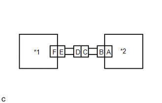
WIRING DIAGRAM

CAUTION / NOTICE / HINT
NOTICE:
After turning the engine switch off, waiting time may be required before disconnecting the cable from the negative (-) battery terminal. Therefore, make sure to read the disconnecting the cable from the negative (-) battery terminal notices before proceeding with work.
Click here .gif)
PROCEDURE
| 1. | CHECK CONNECTION OF CONNECTORS |
(a) Turn the engine switch off.
(b) Disconnect the cable from the negative (-) battery terminal.
CAUTION:
Wait at least 90 seconds after disconnecting the cable from the negative (-) battery terminal to disable the SRS system.
(c) Check that the connectors are properly connected to the airbag sensor assembly, door side airbag sensor RH and rear airbag sensor RH. Also check that the connectors that link the floor wire and front door wire RH are properly connected.
OK:
The connectors are properly connected.
| NG | .gif) | CONNECT CONNECTORS PROPERLY |
|
.gif)
| 2. | CHECK CONNECTORS |
(a) Disconnect the connectors from the airbag sensor assembly, door side airbag sensor RH and rear airbag sensor RH. Also disconnect the connectors that link the floor wire and front door wire RH.
(b) Check that the terminals of the connectors are not deformed or damaged.
OK:
The terminals are not deformed or damaged.
| NG | | REPLACE FLOOR WIRE OR FRONT DOOR WIRE RH |
|
| 3. | CHECK FLOOR WIRE |
| (a) Connect the cable to the negative (-) battery terminal. |
|

(b) Turn the engine switch on (IG).
(c) Measure the voltage according to the value(s) in the table below.
Standard Voltage:
| Tester Connection | Condition | Specified Condition |
|---|---|---|
| R15-4 (BCR+) - Body ground | Engine switch on (IG) | Below 1 V |
| R15-3 (BCR-) - Body ground | Engine switch on (IG) | Below 1 V |
(d) Turn the engine switch off.
(e) Disconnect the cable from the negative (-) battery terminal.
CAUTION:
Wait at least 90 seconds after disconnecting the cable from the negative (-) battery terminal to disable the SRS system.
(f) Using a service wire, connect terminals 25 (BBR+) and 26 (BBR-) of connector B.
NOTICE:
Do not forcibly insert the service wire into the terminals of the connector when connecting the wire.
(g) Measure the resistance according to the value(s) in the table below.
Standard Resistance:
| Tester Connection | Condition | Specified Condition |
|---|---|---|
| R15-4 (BCR+) - R15-3 (BCR-) | Always | Below 1 Ω |
(h) Disconnect the service wire from connector B.
(i) Measure the resistance according to the value(s) in the table below.
Standard Resistance:
| Tester Connection | Condition | Specified Condition |
|---|---|---|
| R15-4 (BCR+) - R15-3 (BCR-) | Always | 1 MΩ or higher |
| R15-4 (BCR+) - Body ground | Always | 1 MΩ or higher |
| R15-3 (BCR-) - Body ground | Always | 1 MΩ or higher |
| NG | | REPLACE FLOOR WIRE |
|
| 4. | CHECK WIRE HARNESS |
| (a) Connect the connectors that link the floor wire and front door wire RH. |
|

(b) Connect the cable to the negative (-) battery terminal.
(c) Turn the engine switch on (IG).
(d) Measure the voltage according to the value(s) in the table below.
Standard Voltage:
| Tester Connection | Condition | Specified Condition |
|---|---|---|
| R15-1 (BDR+) - Body ground | Engine switch on (IG) | Below 1 V |
| R15-2 (BDR-) - Body ground | Engine switch on (IG) | Below 1 V |
(e) Turn the engine switch off.
(f) Disconnect the cable from the negative (-) battery terminal.
CAUTION:
Wait at least 90 seconds after disconnecting the cable from the negative (-) battery terminal to disable the SRS system.
(g) Using a service wire, connect terminals 2 (BDR+) and 1 (BDR-) of connector E.
NOTICE:
Do not forcibly insert the service wire into the terminals of the connector when connecting the wire.
(h) Measure the resistance according to the value(s) in the table below.
Standard Resistance:
| Tester Connection | Condition | Specified Condition |
|---|---|---|
| R15-1 (BDR+) - R15-2 (BDR-) | Always | Below 1 Ω |
(i) Disconnect the service wire from connector E.
(j) Measure the resistance according to the value(s) in the table below.
Standard Resistance:
| Tester Connection | Condition | Specified Condition |
|---|---|---|
| R15-1 (BDR+) - R15-2 (BDR-) | Always | 1 MΩ or higher |
| R15-1 (BDR+) - Body ground | Always | 1 MΩ or higher |
| R15-2 (BDR-) - Body ground | Always | 1 MΩ or higher |
| NG | | GO TO STEP 7 |
|
| 5. | CHECK REAR AIRBAG SENSOR RH |
| (a) Connect the connectors to the door side airbag sensor RH and airbag sensor assembly. |
|

(b) Interchange the rear airbag sensor RH with LH and connect the connectors.
(c) Connect the cable to the negative (-) battery terminal.
(d) Turn the engine switch on (IG), and wait for at least 60 seconds.
(e) Clear the DTCs stored in memory.
Body Electrical > SRS Airbag > Clear DTCs(f) Turn the engine switch off.
(g) Turn the engine switch on (IG), and wait for at least 60 seconds.
(h) Check for DTCs.
Body Electrical > SRS Airbag > Trouble CodesHINT:
Codes other than DTCs B1642, B1643, B1647 and B1648 may be output at this time, but they are not related to this check.
| Result | Proceed to |
|---|---|
| DTC B1642 or B1643 is output. | A |
| DTC B1647 or B1648 is output. | B |
| DTCs B1642, B1643, B1647 and B1648 are not output. | C |
(i) Turn the engine switch off.
(j) Disconnect the cable from the negative (-) battery terminal.
CAUTION:
Wait at least 90 seconds after disconnecting the cable from the negative (-) battery terminal to disable the SRS system.
(k) Return the rear airbag sensor RH and LH to their original positions and connect the connectors.
| B | | REPLACE REAR AIRBAG SENSOR RH |
| C | | USE SIMULATION METHOD TO CHECK |
|
| 6. | CHECK DOOR SIDE AIRBAG SENSOR RH |
| (a) Interchange the door side airbag sensor RH with LH and connect the connectors. |
|
(b) Connect the cable to the negative (-) battery terminal.
(c) Turn the engine switch on (IG), and wait for at least 60 seconds.
(d) Clear the DTCs stored in memory.
Body Electrical > SRS Airbag > Clear DTCs(e) Turn the engine switch off.
(f) Turn the engine switch on (IG), and wait for at least 60 seconds.
(g) Check for DTCs.
Body Electrical > SRS Airbag > Trouble CodesHINT:
Codes other than DTCs B1642, B1643, B1647 and B1648 may be output at this time, but they are not related to this check.
| Result | Proceed to |
|---|---|
| DTC B1642 or B1643 is output. | A |
| DTC B1647 or B1648 is output. | B |
| DTCs B1642, B1643, B1647 and B1648 are not output. | C |
(h) Turn the engine switch off.
(i) Disconnect the cable from the negative (-) battery terminal.
CAUTION:
Wait at least 90 seconds after disconnecting the cable from the negative (-) battery terminal to disable the SRS system.
(j) Return the door side airbag sensor RH and LH to their original positions and connect the connectors.
| A | | REPLACE AIRBAG SENSOR ASSEMBLY |
| B | | REPLACE DOOR SIDE AIRBAG SENSOR RH |
| C | | USE SIMULATION METHOD TO CHECK |
| 7. | CHECK FLOOR WIRE |
| (a) Disconnect the floor wire connector from the front door wire RH. |
|

(b) Connect the cable to the negative (-) battery terminal.
(c) Turn the engine switch on (IG).
(d) Measure the voltage according to the value(s) in the table below.
Standard Voltage:
| Tester Connection | Condition | Specified Condition |
|---|---|---|
| MR1-31 (BDR+) - Body ground | Engine switch on (IG) | Below 1 V |
| MR1-13 (BDR-) - Body ground | Engine switch on (IG) | Below 1 V |
(e) Turn the engine switch off.
(f) Disconnect the cable from the negative (-) battery terminal.
CAUTION:
Wait at least 90 seconds after disconnecting the cable from the negative (-) battery terminal to disable the SRS system.
(g) Using a service wire, connect terminals 1 (BDR+) and 2 (BDR-) of connector B.
NOTICE:
Do not forcibly insert the service wire into the terminals of the connector when connecting the wire.
(h) Measure the resistance according to the value(s) in the table below.
Standard Resistance:
| Tester Connection | Condition | Specified Condition |
|---|---|---|
| MR1-31 (BDR+) - MR1-13 (BDR-) | Always | Below 1 Ω |
(i) Disconnect the service wire from connector B.
(j) Measure the resistance according to the value(s) in the table below.
Standard Resistance:
| Tester Connection | Condition | Specified Condition |
|---|---|---|
| MR1-31 (BDR+) - MR1-13 (BDR-) | Always | 1 MΩ or higher |
| MR1-31 (BDR+) - Body ground | Always | 1 MΩ or higher |
| MR1-13 (BDR-) - Body ground | Always | 1 MΩ or higher |
| OK | | REPLACE FRONT DOOR WIRE RH |
| NG | | REPLACE FLOOR WIRE |
 Curtain Shield Airbag Sensor Initialization Error (LH) (B1638)
DESCRIPTION The side collision sensor LH circuit (bus 1) consists of the airbag sensor assembly, door side airbag sensor LH and rear airbag sensor LH. The door side airbag sensor LH and rear airbag se ...
 Side Satellite Sensor Bus Lost Communication (LH) (B1647,B1648)
DESCRIPTION The side collision sensor LH circuit (bus 1) consists of the airbag sensor assembly, door side airbag sensor LH and rear airbag sensor LH. The door side airbag sensor LH and rear airbag se ...
Other materials:
Lexus RX (RX 350L, RX450h) 2016-2026 Repair Manual > Immobiliser System: Parts Location
PARTS LOCATION ILLUSTRATION *1 ECM - - ILLUSTRATION *A for Lexus Enform Remote Compatible Type - - *1 ENGINE SWITCH *2 CERTIFICATION ECU (SMART KEY ECU ASSEMBLY) *3 ID CODE BOX (IMMOBILISER CODE ECU) *4 STEERING LOCK ECU (STEERING LOCK ACTUATOR OR UPPER BRA ...
Lexus RX (RX 350L, RX450h) 2016-2026 Repair Manual > Sfi System: Lack of Power
DESCRIPTION Problem Symptom Suspected Area Trouble Area
Engine speed fluctuation due to abnormal combustion
Idle speed too low or high
Strong engine vibration due to above symptoms
Ignition malfunction
Deviation in air fuel ratio (Excessive or insufficient intake air volume ...
Lexus RX (RX 350L, RX450h) 2016-{YEAR} Owners Manual
- For your information
- Pictorial index
- For safety and security
- Instrument cluster
- Operation of each component
- Driving
- Lexus Display Audio system
- Interior features
- Maintenance and care
- When trouble arises
- Vehicle specifications
- For owners
Lexus RX (RX 350L, RX450h) 2016-{YEAR} Repair Manual

0.0112