Lexus RX (RX 350L, RX450h) 2016-2026 Repair Manual: Side Satellite Sensor Bus Lost Communication (LH) (B1647,B1648)
DESCRIPTION
The side collision sensor LH circuit (bus 1) consists of the airbag sensor assembly, door side airbag sensor LH and rear airbag sensor LH.
The door side airbag sensor LH and rear airbag sensor LH detect impacts to the vehicle and send signals to the airbag sensor assembly to determine if the airbags and pretensioners should be deployed.
These DTCs are stored when a malfunction is detected in the side collision sensor LH circuit (bus 1).
| DTC No. | Detection Item | DTC Detection Condition | Trouble Area | Warning Indicate | Test Mode / Check Mode |
|---|---|---|---|---|---|
| B1647 | Side Satellite Sensor Bus Lost Communication (LH) |
|
| Comes on | Does not apply to test/check mode |
| B1648 | Side Satellite Sensor Bus Initialization Error (LH) |
|
| Comes on | Does not apply to test/check mode |
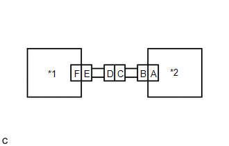
WIRING DIAGRAM
.png)
CAUTION / NOTICE / HINT
NOTICE:
After turning the engine switch off, waiting time may be required before disconnecting the cable from the negative (-) battery terminal. Therefore, make sure to read the disconnecting the cable from the negative (-) battery terminal notices before proceeding with work.
Click here .gif)
PROCEDURE
| 1. | CHECK CONNECTION OF CONNECTORS |
(a) Turn the engine switch off.
(b) Disconnect the cable from the negative (-) battery terminal.
CAUTION:
Wait at least 90 seconds after disconnecting the cable from the negative (-) battery terminal to disable the SRS system.
(c) Check that the connectors are properly connected to the airbag sensor assembly, door side airbag sensor LH and rear airbag sensor LH. Also check that the connectors that link the No. 2 floor wire and front door wire LH are properly connected.
OK:
The connectors are properly connected.
| NG | .gif) | CONNECT CONNECTORS PROPERLY |
|
.gif)
| 2. | CHECK CONNECTORS |
(a) Disconnect the connectors from the airbag sensor assembly, door side airbag sensor LH and rear airbag sensor LH. Also disconnect the connectors that link the No. 2 floor wire and front door wire LH.
(b) Check that the terminals of the connectors are not deformed or damaged.
OK:
The terminals are not deformed or damaged.
| NG | | REPLACE NO. 2 FLOOR WIRE OR FRONT DOOR WIRE LH |
|
| 3. | CHECK NO. 2 FLOOR WIRE |
| (a) Connect the cable to the negative (-) battery terminal. |
|
.png)
(b) Turn the engine switch on (IG).
(c) Measure the voltage according to the value(s) in the table below.
Standard Voltage:
| Tester Connection | Condition | Specified Condition |
|---|---|---|
| S15-4 (BCL+) - Body ground | Engine switch on (IG) | Below 1 V |
| S15-3 (BCL-) - Body ground | Engine switch on (IG) | Below 1 V |
(d) Turn the engine switch off.
(e) Disconnect the cable from the negative (-) battery terminal.
CAUTION:
Wait at least 90 seconds after disconnecting the cable from the negative (-) battery terminal to disable the SRS system.
(f) Using a service wire, connect terminals 32 (BBL+) and 31 (BBL-) of connector B.
NOTICE:
Do not forcibly insert the service wire into the terminals of the connector when connecting the wire.
(g) Measure the resistance according to the value(s) in the table below.
Standard Resistance:
| Tester Connection | Condition | Specified Condition |
|---|---|---|
| S15-4 (BCL+) - S15-3 (BCL-) | Always | Below 1 Ω |
(h) Disconnect the service wire from connector B.
(i) Measure the resistance according to the value(s) in the table below.
Standard Resistance:
| Tester Connection | Condition | Specified Condition |
|---|---|---|
| S15-4 (BCL+) - S15-3 (BCL-) | Always | 1 MΩ or higher |
| S15-4 (BCL+) - Body ground | Always | 1 MΩ or higher |
| S15-3 (BCL-) - Body ground | Always | 1 MΩ or higher |
| NG | | REPLACE NO. 2 FLOOR WIRE |
|
| 4. | CHECK WIRE HARNESS |
| (a) Connect the connectors that link the No. 2 floor wire and front door wire LH. |
|
.png)
(b) Connect the cable to the negative (-) battery terminal.
(c) Turn the engine switch on (IG).
(d) Measure the voltage according to the value(s) in the table below.
Standard Voltage:
| Tester Connection | Condition | Specified Condition |
|---|---|---|
| S15-1 (BDL+) - Body ground | Engine switch on (IG) | Below 1 V |
| S15-2 (BDL-) - Body ground | Engine switch on (IG) | Below 1 V |
(e) Turn the engine switch off.
(f) Disconnect the cable from the negative (-) battery terminal.
CAUTION:
Wait at least 90 seconds after disconnecting the cable from the negative (-) battery terminal to disable the SRS system.
(g) Using a service wire, connect terminals 2 (BDL+) and 1 (BDL-) of connector E.
NOTICE:
Do not forcibly insert the service wire into the terminals of the connector when connecting the wire.
(h) Measure the resistance according to the value(s) in the table below.
Standard Resistance:
| Tester Connection | Condition | Specified Condition |
|---|---|---|
| S15-1 (BDL+) - S15-2 (BDL-) | Always | Below 1 Ω |
(i) Disconnect the service wire from connector E.
(j) Measure the resistance according to the value(s) in the table below.
Standard Resistance:
| Tester Connection | Condition | Specified Condition |
|---|---|---|
| S15-1 (BDL+) - S15-2 (BDL-) | Always | 1 MΩ or higher |
| S15-1 (BDL+) - Body ground | Always | 1 MΩ or higher |
| S15-2 (BDL-) - Body ground | Always | 1 MΩ or higher |
| NG | | GO TO STEP 7 |
|
| 5. | CHECK REAR AIRBAG SENSOR LH |
| (a) Connect the connectors to the door side airbag sensor LH and airbag sensor assembly. |
|
.png)
(b) Interchange the rear airbag sensor LH with RH and connect the connectors.
(c) Connect the cable to the negative (-) battery terminal.
(d) Turn the engine switch on (IG), and wait for at least 60 seconds.
(e) Clear the DTCs stored in memory.
Body Electrical > SRS Airbag > Clear DTCs(f) Turn the engine switch off.
(g) Turn the engine switch on (IG), and wait for at least 60 seconds.
(h) Check for DTCs.
Body Electrical > SRS Airbag > Trouble CodesHINT:
Codes other than DTCs B1642, B1643, B1647 and B1648 may be output at this time, but they are not related to this check.
| Result | Proceed to |
|---|---|
| DTC B1647 or B1648 is output. | A |
| DTC B1642 or B1643 is output. | B |
| DTCs B1642, B1643, B1647 and B1648 are not output. | C |
(i) Turn the engine switch off.
(j) Disconnect the cable from the negative (-) battery terminal.
CAUTION:
Wait at least 90 seconds after disconnecting the cable from the negative (-) battery terminal to disable the SRS system.
(k) Return the rear airbag sensor LH and RH to their original positions and connect the connectors.
| B | | REPLACE REAR AIRBAG SENSOR LH |
| C | | USE SIMULATION METHOD TO CHECK |
|
| 6. | CHECK DOOR SIDE AIRBAG SENSOR LH |
| (a) Interchange the door side airbag sensor LH with RH and connect the connectors. |
|
(b) Connect the cable to the negative (-) battery terminal.
(c) Turn the engine switch on (IG), and wait for at least 60 seconds.
(d) Clear the DTCs stored in memory.
Body Electrical > SRS Airbag > Clear DTCs(e) Turn the engine switch off.
(f) Turn the engine switch on (IG), and wait for at least 60 seconds.
(g) Check for DTCs.
Body Electrical > SRS Airbag > Trouble CodesHINT:
Codes other than DTCs B1642, B1643, B1647 and B1648 may be output at this time, but they are not related to this check.
| Result | Proceed to |
|---|---|
| DTC B1647 or B1648 is output. | A |
| DTC B1642 or B1643 is output. | B |
| DTCs B1642, B1643, B1647 and B1648 are not output. | C |
(h) Turn the engine switch off.
(i) Disconnect the cable from the negative (-) battery terminal.
CAUTION:
Wait at least 90 seconds after disconnecting the cable from the negative (-) battery terminal to disable the SRS system.
(j) Return the door side airbag sensor LH and RH to their original positions and connect the connectors.
| A | | REPLACE AIRBAG SENSOR ASSEMBLY |
| B | | REPLACE DOOR SIDE AIRBAG SENSOR LH |
| C | | USE SIMULATION METHOD TO CHECK |
| 7. | CHECK NO. 2 FLOOR WIRE |
| (a) Disconnect the No. 2 floor wire connector from the front door wire LH. |
|
.png)
(b) Connect the cable to the negative (-) battery terminal.
(c) Turn the engine switch on (IG).
(d) Measure the voltage according to the value(s) in the table below.
Standard Voltage:
| Tester Connection | Condition | Specified Condition |
|---|---|---|
| NS1-21 (BDL+) - Body ground | Engine switch on (IG) | Below 1 V |
| NS1-39 (BDL-) - Body ground | Engine switch on (IG) | Below 1 V |
(e) Turn the engine switch off.
(f) Disconnect the cable from the negative (-) battery terminal.
CAUTION:
Wait at least 90 seconds after disconnecting the cable from the negative (-) battery terminal to disable the SRS system.
(g) Using a service wire, connect terminals 1 (BDL+) and 2 (BDL-) of connector B.
NOTICE:
Do not forcibly insert the service wire into the terminals of the connector when connecting the wire.
(h) Measure the resistance according to the value(s) in the table below.
Standard Resistance:
| Tester Connection | Condition | Specified Condition |
|---|---|---|
| NS1-21 (BDL+) - NS1-39 (BDL-) | Always | Below 1 Ω |
(i) Disconnect the service wire from connector B.
(j) Measure the resistance according to the value(s) in the table below.
Standard Resistance:
| Tester Connection | Condition | Specified Condition |
|---|---|---|
| NS1-21 (BDL+) - NS1-39 (BDL-) | Always | 1 MΩ or higher |
| NS1-21 (BDL+) - Body ground | Always | 1 MΩ or higher |
| NS1-39 (BDL-) - Body ground | Always | 1 MΩ or higher |
| OK | | REPLACE FRONT DOOR WIRE LH |
| NG | | REPLACE NO. 2 FLOOR WIRE |
 Side Satellite Sensor Bus Lost Communication (RH) (B1642,B1643)
DESCRIPTION The side collision sensor RH circuit (bus 1) consists of the airbag sensor assembly, door side airbag sensor RH and rear airbag sensor RH. The door side airbag sensor RH and rear airbag se ...
 Occupant Classification System Malfunction (B1650,B165A)
DESCRIPTION The airbag sensor assembly and occupant detection ECU communicate via CAN communication. When the occupant detection ECU stores DTC B1771, B1780, B1782, B1795, B1798, B1799, U0125 or U0129 ...
Other materials:
Lexus RX (RX 350L, RX450h) 2016-2026 Repair Manual > Safety Connect System: Backup Battery Internal Electronic Failure (B15CC49)
DESCRIPTION This DTC is set when the DCM (telematics transceiver) detects one of the following:
The mobilephone battery voltage drops or the mobilephone battery malfunctions.
The mobilephone battery temperature is (temporarily) high.
DTC No. Detection Item DTC Detection Condition Tr ...
Lexus RX (RX 350L, RX450h) 2016-2026 Repair Manual > 2gr-fks (starting): Relay
On-vehicle InspectionON-VEHICLE INSPECTION PROCEDURE 1. INSPECT ST RELAY (a) Check the resistance. (1) Measure the resistance according to the value(s) in the table below. Standard Resistance: Tester Connection Condition Specified Condition 3 - 5 Battery voltage not applied to termi ...
Lexus RX (RX 350L, RX450h) 2016-{YEAR} Owners Manual
- For your information
- Pictorial index
- For safety and security
- Instrument cluster
- Operation of each component
- Driving
- Lexus Display Audio system
- Interior features
- Maintenance and care
- When trouble arises
- Vehicle specifications
- For owners
Lexus RX (RX 350L, RX450h) 2016-{YEAR} Repair Manual

0.0103