Lexus RX (RX 350L, RX450h) 2016-2026 Repair Manual: P Seat Airbag Active Mode Indicator (B1660)
DESCRIPTION
The passenger airbag ON/OFF indicator circuit consists of the airbag sensor assembly and passenger airbag ON/OFF indicator (radio receiver assembly).
The passenger airbag ON/OFF indicator indicates the operation condition of the instrument panel passenger airbag assembly and front seat cushion airbag assembly RH.
DTC B1660 is stored when a malfunction is detected in the passenger airbag ON/OFF indicator circuit.
| DTC No. | Detection Item | DTC Detection Condition | Trouble Area | Warning Indicate | Test Mode / Check Mode |
|---|---|---|---|---|---|
| B1660 | P Seat Airbag Active Mode Indicator |
| for TMC Made:
for TMMC Made:
| Comes on | Does not apply to test/check mode |
WIRING DIAGRAM
for TMC Made: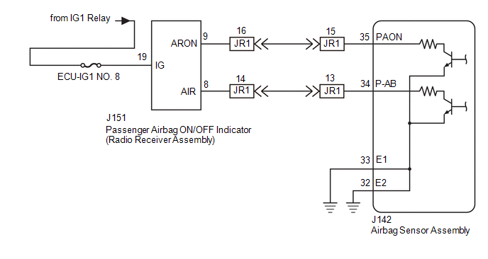 for TMMC Made:
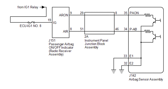
CAUTION / NOTICE / HINT
NOTICE:
-
After turning the engine switch off, waiting time may be required before disconnecting the cable from the negative (-) battery terminal. Therefore, make sure to read the disconnecting the cable from the negative (-) battery terminal notices before proceeding with work.
Click here
.gif)
- Inspect the fuses for circuits related to this system before performing the following procedure.
PROCEDURE
| 1. | CHECK VEHICLE CONDITION |
(a) Choose the model to be inspected.
| Result | Proceed to |
|---|---|
| for TMC Made | A |
| for TMMC Made | B |
| B | .gif) | GO TO STEP 16 |
|
.gif)
| 2. | CHECK PASSENGER AIRBAG ON/OFF INDICATOR CONDITION |
(a) Turn the engine switch on (IG).
(b) Check the passenger airbag ON/OFF indicator operation.
HINT:
Refer to the normal condition of the passenger airbag ON/OFF indicator.
Click here
| Result | Proceed to |
|---|---|
| Passenger airbag ON/OFF indicator illumination is always on. | A |
| Passenger airbag ON/OFF indicator illumination is always off. | B |
| B | | GO TO STEP 9 |
|
| 3. | CHECK CONNECTION OF CONNECTORS |
(a) Turn the engine switch off.
(b) Disconnect the cable from the negative (-) battery terminal.
CAUTION:
Wait at least 90 seconds after disconnecting the cable from the negative (-) battery terminal to disable the SRS system.
(c) Check that the connectors are properly connected to the airbag sensor assembly and radio receiver assembly. Also check that the connectors that link the floor wire and instrument panel wire are properly connected.
OK:
The connectors are properly connected.
| NG | | CONNECT CONNECTORS PROPERLY |
|
| 4. | CHECK CONNECTORS |
(a) Disconnect the connectors from the airbag sensor assembly and radio receiver assembly. Also disconnect the connectors that link the floor wire and instrument panel wire.
(b) Check that the terminals of the connectors are not deformed or damaged.
OK:
The terminals are not deformed or damaged.
| NG | | REPLACE INSTRUMENT PANEL WIRE OR FLOOR WIRE |
|
| 5. | CHECK PASSENGER AIRBAG ON/OFF INDICATOR CONDITION |
(a) Connect the connector to the radio receiver assembly.
(b) Connect the connectors that link the floor wire and instrument panel wire.
(c) Connect the cable to the negative (-) battery terminal.
(d) Turn the engine switch on (IG).
(e) Check the passenger airbag ON/OFF indicator operation.
OK:
The passenger airbag ON/OFF indicator does not come on.
| NG | | GO TO STEP 7 |
|
| 6. | CHECK DTC |
| (a) Turn the engine switch off. |
|
(b) Disconnect the cable from the negative (-) battery terminal.
CAUTION:
Wait at least 90 seconds after disconnecting the cable from the negative (-) battery terminal to disable the SRS system.
(c) Connect the connector to the airbag sensor assembly.
(d) Connect the cable to the negative (-) battery terminal.
(e) Turn the engine switch on (IG), and wait for at least 60 seconds.
(f) Clear the DTCs stored in memory.
Body Electrical > SRS Airbag > Clear DTCs(g) Turn the engine switch off.
(h) Turn the engine switch on (IG), and wait for at least 60 seconds.
(i) Check for DTCs.
Body Electrical > SRS Airbag > Trouble CodesOK:
DTC B1660 is not output.
HINT:
Codes other than DTC B1660 may be output at this time, but they are not related to this check.
| OK | | USE SIMULATION METHOD TO CHECK |
| NG | | REPLACE AIRBAG SENSOR ASSEMBLY |
| 7. | CHECK WIRE HARNESS |
(a) Turn the engine switch off.
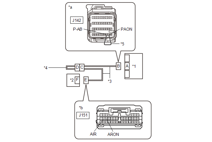
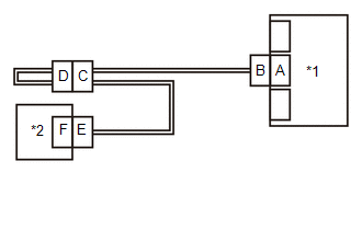
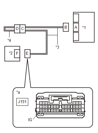
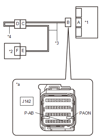
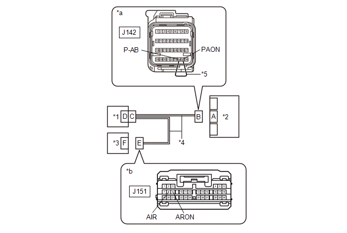
| *1 | Airbag Sensor Assembly | *2 | Radio Receiver Assembly |
| *3 | Instrument Panel Wire | *4 | Floor Wire |
| *5 | Service Wire | - | - |
| *a | Front view of wire harness connector (to Airbag Sensor Assembly) | *b | Front view of wire harness connector (to Radio Receiver Assembly) |
(b) Disconnect the cable from the negative (-) battery terminal.
CAUTION:
Wait at least 90 seconds after disconnecting the cable from the negative (-) battery terminal to disable the SRS system.
(c) Disconnect the connector from the radio receiver assembly.
(d) Connect the cable to the negative (-) battery terminal.
(e) Turn the engine switch on (IG).
(f) Measure the voltage according to the value(s) in the table below.
Standard Voltage:
| Tester Connection | Condition | Specified Condition |
|---|---|---|
| J151-9 (ARON) - Body ground | Engine switch on (IG) | Below 1 V |
| J151-8 (AIR) - Body ground | Engine switch on (IG) | Below 1 V |
(g) Turn the engine switch off.
(h) Disconnect the cable from the negative (-) battery terminal.
CAUTION:
Wait at least 90 seconds after disconnecting the cable from the negative (-) battery terminal to disable the SRS system.
(i) Using a service wire, connect terminals 35 (PAON) and 34 (P-AB) of connector B.
NOTICE:
Do not forcibly insert the service wire into the terminals of the connector when connecting the wire.
(j) Measure the resistance according to the value(s) in the table below.
Standard Resistance:
| Tester Connection | Condition | Specified Condition |
|---|---|---|
| J151-9 (ARON) - J151-8 (AIR) | Always | Below 1 Ω |
(k) Disconnect the service wire from connector B.
(l) Measure the resistance according to the value(s) in the table below.
Standard Resistance:
| Tester Connection | Condition | Specified Condition |
|---|---|---|
| J151-9 (ARON) - J151-8 (AIR) | Always | 1 MΩ or higher |
| J151-9 (ARON) - Body ground | Always | 1 MΩ or higher |
| J151-8 (AIR) - Body ground | Always | 1 MΩ or higher |
| OK | | REPLACE RADIO RECEIVER ASSEMBLY |
|
| 8. | CHECK FLOOR WIRE |
(a) Disconnect the floor wire connector from the instrument panel wire.
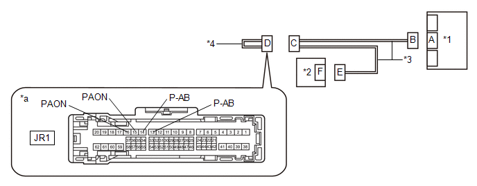
| *1 | Airbag Sensor Assembly | *2 | Radio Receiver Assembly |
| *3 | Instrument Panel Wire | *4 | Floor Wire |
| *a | Front view of wire harness connector (to Instrument Panel Wire) | - | - |
(b) Measure the resistance according to the value(s) in the table below.
Standard Resistance:
| Tester Connection | Condition | Specified Condition |
|---|---|---|
| JR1-15 (PAON) - JR1-16 (PAON) | Always | Below 1 Ω |
| JR1-13 (P-AB) - JR1-14 (P-AB) | Always | Below 1 Ω |
| JR1-15 (PAON) - Body ground or other terminals | Always | 1 MΩ or higher |
| JR1-13 (P-AB) - Body ground or other terminals | Always | 1 MΩ or higher |
| OK | | REPLACE INSTRUMENT PANEL WIRE |
| NG | | REPLACE FLOOR WIRE |
| 9. | CHECK CONNECTION OF CONNECTORS |
(a) Turn the engine switch off.
(b) Disconnect the cable from the negative (-) battery terminal.
CAUTION:
Wait at least 90 seconds after disconnecting the cable from the negative (-) battery terminal to disable the SRS system.
(c) Check that the connectors are properly connected to the airbag sensor assembly and radio receiver assembly. Also check that the connectors that link the floor wire and instrument panel wire are properly connected.
OK:
The connectors are properly connected.
| NG | | CONNECT CONNECTORS PROPERLY |
|
| 10. | CHECK CONNECTORS |
(a) Disconnect the connectors from the airbag sensor assembly and radio receiver assembly. Also disconnect the connectors that link the floor wire and instrument panel wire.
(b) Check that the terminals of the connectors are not deformed or damaged.
OK:
The terminals are not deformed or damaged.
| NG | | REPLACE INSTRUMENT PANEL WIRE OR FLOOR WIRE |
|
| 11. | CHECK WIRE HARNESS |
(a) Connect the connectors that link the floor wire and instrument panel wire.
| *1 | Airbag Sensor Assembly | *2 | Radio Receiver Assembly |
| *3 | Instrument Panel Wire | *4 | Floor Wire |
| *5 | Service Wire | - | - |
| *a | Front view of wire harness connector (to Airbag Sensor Assembly) | *b | Front view of wire harness connector (to Radio Receiver Assembly) |
(b) Connect the cable to the negative (-) battery terminal.
(c) Turn the engine switch on (IG).
(d) Measure the voltage according to the value(s) in the table below.
Standard Voltage:
| Tester Connection | Condition | Specified Condition |
|---|---|---|
| J151-9 (ARON) - Body ground | Engine switch on (IG) | Below 1 V |
| J151-8 (AIR) - Body ground | Engine switch on (IG) | Below 1 V |
(e) Turn the engine switch off.
(f) Disconnect the cable from the negative (-) battery terminal.
CAUTION:
Wait at least 90 seconds after disconnecting the cable from the negative (-) battery terminal to disable the SRS system.
(g) Using a service wire, connect terminals 35 (PAON) and 34 (P-AB) of connector B.
NOTICE:
Do not forcibly insert the service wire into the terminals of the connector when connecting the wire.
(h) Measure the resistance according to the value(s) in the table below.
Standard Resistance:
| Tester Connection | Condition | Specified Condition |
|---|---|---|
| J151-9 (ARON) - J151-8 (AIR) | Always | Below 1 Ω |
(i) Disconnect the service wire from connector B.
(j) Measure the resistance according to the value(s) in the table below.
Standard Resistance:
| Tester Connection | Condition | Specified Condition |
|---|---|---|
| J151-9 (ARON) - J151-8 (AIR) | Always | 1 MΩ or higher |
| J151-9 (ARON) - Body ground | Always | 1 MΩ or higher |
| J151-8 (AIR) - Body ground | Always | 1 MΩ or higher |
| NG | | GO TO STEP 15 |
|
| 12. | CHECK PASSENGER AIRBAG ON/OFF INDICATOR (SOURCE VOLTAGE) |
| (a) Connect the cable to the negative (-) battery terminal. |
|
(b) Turn the engine switch on (IG).
(c) Measure the voltage according to the value(s) in the table below.
Standard Voltage:
| Tester Connection | Condition | Specified Condition |
|---|---|---|
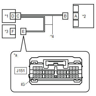
| J151-19 (IG) - Body ground | Engine switch on (IG) | 11 to 14 V |
(d) Turn the engine switch off.
(e) Disconnect the cable from the negative (-) battery terminal.
CAUTION:
Wait at least 90 seconds after disconnecting the cable from the negative (-) battery terminal to disable the SRS system.
| NG | | REPLACE WIRE HARNESS OR BATTERY |
|
| 13. | CHECK PASSENGER AIRBAG ON/OFF INDICATOR |
| (a) Connect the connector to the radio receiver assembly. |
|
(b) Connect the cable to the negative (-) battery terminal.
(c) Turn the engine switch on (IG).
(d) Check the passenger airbag ON/OFF indicator according to the conditions in the table below.
OK:
| Terminal Connection | Condition | Specified Condition |
|---|---|---|
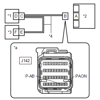
| J142-35 (PAON) - Body ground | Engine switch on (IG) | "ON" comes on |
| J142-34 (P-AB) - Body ground | Engine switch on (IG) | "OFF" comes on |
(e) Turn the engine switch off.
(f) Disconnect the cable from the negative (-) battery terminal.
CAUTION:
Wait at least 90 seconds after disconnecting the cable from the negative (-) battery terminal to disable the SRS system.
| NG | | REPLACE RADIO RECEIVER ASSEMBLY |
|
| 14. | CHECK DTC |
| (a) Connect the connector to the airbag sensor assembly. |
|
(b) Connect the cable to the negative (-) battery terminal.
(c) Turn the engine switch on (IG), and wait for at least 60 seconds.
(d) Clear the DTCs stored in memory.
Body Electrical > SRS Airbag > Clear DTCs(e) Turn the engine switch off.
(f) Turn the engine switch on (IG), and wait for at least 60 seconds.
(g) Check for DTCs.
Body Electrical > SRS Airbag > Trouble CodesOK:
DTC B1660 is not output.
HINT:
Codes other than DTC B1660 may be output at this time, but they are not related to this check.
| OK | | USE SIMULATION METHOD TO CHECK |
| NG | | REPLACE AIRBAG SENSOR ASSEMBLY |
| 15. | CHECK FLOOR WIRE |
(a) Disconnect the floor wire connector from the instrument panel wire.
| *1 | Airbag Sensor Assembly | *2 | Radio Receiver Assembly |
| *3 | Instrument Panel Wire | *4 | Floor Wire |
| *a | Front view of wire harness connector (to Instrument Panel Wire) | - | - |
(b) Measure the resistance according to the value(s) in the table below.
Standard Resistance:
| Tester Connection | Condition | Specified Condition |
|---|---|---|
| JR1-15 (PAON) - JR1-16 (PAON) | Always | Below 1 Ω |
| JR1-13 (P-AB) - JR1-14 (P-AB) | Always | Below 1 Ω |
| JR1-15 (PAON) - Body ground or other terminals | Always | 1 MΩ or higher |
| JR1-13 (P-AB) - Body ground or other terminals | Always | 1 MΩ or higher |
| OK | | REPLACE INSTRUMENT PANEL WIRE |
| NG | | REPLACE FLOOR WIRE |
| 16. | CHECK PASSENGER AIRBAG ON/OFF INDICATOR CONDITION |
(a) Turn the engine switch on (IG).
(b) Check the passenger airbag ON/OFF indicator operation.
HINT:
Refer to the normal condition of the passenger airbag ON/OFF indicator.
Click here
| Result | Proceed to |
|---|---|
| Passenger airbag ON/OFF indicator illumination is always on. | A |
| Passenger airbag ON/OFF indicator illumination is always off. | B |
| B | | GO TO STEP 23 |
|
| 17. | CHECK CONNECTION OF CONNECTORS |
(a) Turn the engine switch off.
(b) Disconnect the cable from the negative (-) battery terminal.
CAUTION:
Wait at least 90 seconds after disconnecting the cable from the negative (-) battery terminal to disable the SRS system.
(c) Check that the connectors are properly connected to the airbag sensor assembly, radio receiver assembly and instrument panel junction block assembly.
OK:
The connectors are properly connected.
| NG | | CONNECT CONNECTORS PROPERLY |
|
| 18. | CHECK CONNECTORS |
(a) Disconnect the connectors from the airbag sensor assembly, radio receiver assembly and instrument panel junction block assembly.
(b) Check that the terminals of the connectors are not deformed or damaged.
OK:
The terminals are not deformed or damaged.
| NG | | REPLACE INSTRUMENT PANEL WIRE |
|
| 19. | CHECK PASSENGER AIRBAG ON/OFF INDICATOR CONDITION |
(a) Connect the connector to the radio receiver assembly and instrument panel junction block assembly.
(b) Connect the cable to the negative (-) battery terminal.
(c) Turn the engine switch on (IG).
(d) Check the passenger airbag ON/OFF indicator operation.
OK:
The passenger airbag ON/OFF indicator does not come on.
| NG | | GO TO STEP 21 |
|
| 20. | CHECK DTC |
| (a) Turn the engine switch off. |
|
(b) Disconnect the cable from the negative (-) battery terminal.
CAUTION:
Wait at least 90 seconds after disconnecting the cable from the negative (-) battery terminal to disable the SRS system.
(c) Connect the connector to the airbag sensor assembly.
(d) Connect the cable to the negative (-) battery terminal.
(e) Turn the engine switch on (IG), and wait for at least 60 seconds.
(f) Clear the DTCs stored in memory.
Body Electrical > SRS Airbag > Clear DTCs(g) Turn the engine switch off.
(h) Turn the engine switch on (IG), and wait for at least 60 seconds.
(i) Check for DTCs.
Body Electrical > SRS Airbag > Trouble CodesOK:
DTC B1660 is not output.
HINT:
Codes other than DTC B1660 may be output at this time, but they are not related to this check.
| OK | | USE SIMULATION METHOD TO CHECK |
| NG | | REPLACE AIRBAG SENSOR ASSEMBLY |
| 21. | CHECK WIRE HARNESS |
(a) Turn the engine switch off.
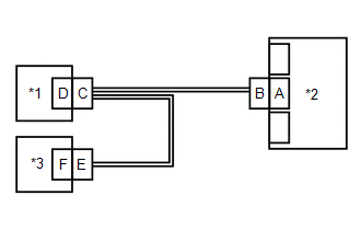
| *1 | Instrument Panel Junction Block Assembly | *2 | Airbag Sensor Assembly |
| *3 | Radio Receiver Assembly | *4 | Instrument Panel Wire |
| *5 | Service Wire | - | - |
| *a | Front view of wire harness connector (to Airbag Sensor Assembly) | *b | Front view of wire harness connector (to Radio Receiver Assembly) |
(b) Disconnect the cable from the negative (-) battery terminal.
CAUTION:
Wait at least 90 seconds after disconnecting the cable from the negative (-) battery terminal to disable the SRS system.
(c) Disconnect the connector from the radio receiver assembly.
(d) Connect the cable to the negative (-) battery terminal.
(e) Turn the engine switch on (IG).
(f) Measure the voltage according to the value(s) in the table below.
Standard Voltage:
| Tester Connection | Condition | Specified Condition |
|---|---|---|
| J151-9 (ARON) - Body ground | Engine switch on (IG) | Below 1 V |
| J151-8 (AIR) - Body ground | Engine switch on (IG) | Below 1 V |
(g) Turn the engine switch off.
(h) Disconnect the cable from the negative (-) battery terminal.
CAUTION:
Wait at least 90 seconds after disconnecting the cable from the negative (-) battery terminal to disable the SRS system.
(i) Using a service wire, connect terminals 35 (PAON) and 34 (P-AB) of connector B.
NOTICE:
Do not forcibly insert the service wire into the terminals of the connector when connecting the wire.
(j) Measure the resistance according to the value(s) in the table below.
Standard Resistance:
| Tester Connection | Condition | Specified Condition |
|---|---|---|
| J151-9 (ARON) - J151-8 (AIR) | Always | Below 1 Ω |
(k) Disconnect the service wire from connector B.
(l) Measure the resistance according to the value(s) in the table below.
Standard Resistance:
| Tester Connection | Condition | Specified Condition |
|---|---|---|
| J151-9 (ARON) - J151-8 (AIR) | Always | 1 MΩ or higher |
| J151-9 (ARON) - Body ground | Always | 1 MΩ or higher |
| J151-8 (AIR) - Body ground | Always | 1 MΩ or higher |
| OK | | REPLACE RADIO RECEIVER ASSEMBLY |
|
| 22. | CHECK INSTRUMENT PANEL WIRE |
(a) Disconnect the connector from the instrument panel junction block assembly.
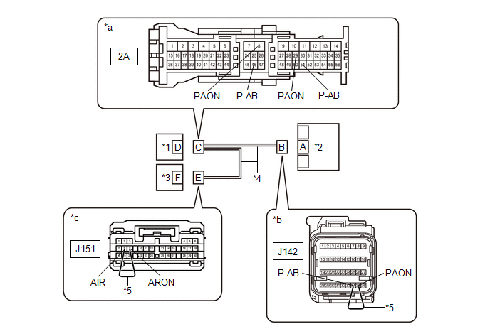
| *1 | Instrument Panel Junction Block Assembly | *2 | Airbag Sensor Assembly |
| *3 | Radio Receiver Assembly | *4 | Instrument Panel Wire |
| *5 | Service Wire | - | - |
| *a | Front view of wire harness connector (to Instrument Panel Junction Block Assembly) | *b | Front view of wire harness connector (to Airbag Sensor Assembly) |
| *c | Front view of wire harness connector (to Radio Receiver Assembly) | - | - |
(b) Using a service wire, connect terminals 35 (PAON) and 34 (P-AB) of connector B.
NOTICE:
Do not forcibly insert the service wire into the terminals of the connector when connecting the wire.
(c) Measure the resistance according to the value(s) in the table below.
Standard Resistance:
| Tester Connection | Condition | Specified Condition |
|---|---|---|
| 2A-8 (PAON) - 2A-46 (P-AB) | Always | Below 1 Ω |
(d) Disconnect the service wire from connector B.
(e) Using a service wire, connect terminals 9 (ARON) and 8 (AIR) of connector E.
NOTICE:
Do not forcibly insert the service wire into the terminals of the connector when connecting the wire.
(f) Measure the resistance according to the value(s) in the table below.
Standard Resistance:
| Tester Connection | Condition | Specified Condition |
|---|---|---|
| 2A-29 (PAON) - 2A-51 (P-AB) | Always | Below 1 Ω |
(g) Disconnect the service wire from connector E.
(h) Measure the resistance according to the value(s) in the table below.
Standard Resistance:
| Tester Connection | Condition | Specified Condition |
|---|---|---|
| 2A-8 (PAON) - Body ground or other terminals | Always | 1 MΩ or higher |
| 2A-29 (PAON) - Body ground or other terminals | Always | 1 MΩ or higher |
| 2A-46 (P-AB) - Body ground or other terminals | Always | 1 MΩ or higher |
| 2A-51 (P-AB) - Body ground or other terminals | Always | 1 MΩ or higher |
| OK | | REPLACE INSTRUMENT PANEL JUNCTION BLOCK ASSEMBLY |
| NG | | REPLACE INSTRUMENT PANEL WIRE |
| 23. | CHECK CONNECTION OF CONNECTORS |
(a) Turn the engine switch off.
(b) Disconnect the cable from the negative (-) battery terminal.
CAUTION:
Wait at least 90 seconds after disconnecting the cable from the negative (-) battery terminal to disable the SRS system.
(c) Check that the connectors are properly connected to the airbag sensor assembly, radio receiver assembly and instrument panel junction block assembly.
OK:
The connectors are properly connected.
| NG | | CONNECT CONNECTORS PROPERLY |
|
| 24. | CHECK CONNECTORS |
(a) Disconnect the connectors from the airbag sensor assembly, radio receiver assembly and instrument panel junction block assembly.
(b) Check that the terminals of the connectors are not deformed or damaged.
OK:
The terminals are not deformed or damaged.
| NG | | REPLACE INSTRUMENT PANEL WIRE |
|
| 25. | CHECK WIRE HARNESS |
(a) Connect the connector to the instrument panel junction block assembly.
| *1 | Instrument Panel Junction Block Assembly | *2 | Airbag Sensor Assembly |
| *3 | Radio Receiver Assembly | *4 | Instrument Panel Wire |
| *5 | Service Wire | - | - |
| *a | Front view of wire harness connector (to Airbag Sensor Assembly) | *b | Front view of wire harness connector (to Radio Receiver Assembly) |
(b) Connect the cable to the negative (-) battery terminal.
(c) Turn the engine switch on (IG).
(d) Measure the voltage according to the value(s) in the table below.
Standard Voltage:
| Tester Connection | Condition | Specified Condition |
|---|---|---|
| J151-9 (ARON) - Body ground | Engine switch on (IG) | Below 1 V |
| J151-8 (AIR) - Body ground | Engine switch on (IG) | Below 1 V |
(e) Turn the engine switch off.
(f) Disconnect the cable from the negative (-) battery terminal.
CAUTION:
Wait at least 90 seconds after disconnecting the cable from the negative (-) battery terminal to disable the SRS system.
(g) Using a service wire, connect terminals 35 (PAON) and 34 (P-AB) of connector B.
NOTICE:
Do not forcibly insert the service wire into the terminals of the connector when connecting the wire.
(h) Measure the resistance according to the value(s) in the table below.
Standard Resistance:
| Tester Connection | Condition | Specified Condition |
|---|---|---|
| J151-9 (ARON) - J151-8 (AIR) | Always | Below 1 Ω |
(i) Disconnect the service wire from connector B.
(j) Measure the resistance according to the value(s) in the table below.
Standard Resistance:
| Tester Connection | Condition | Specified Condition |
|---|---|---|
| J151-9 (ARON) - J151-8 (AIR) | Always | 1 MΩ or higher |
| J151-9 (ARON) - Body ground | Always | 1 MΩ or higher |
| J151-8 (AIR) - Body ground | Always | 1 MΩ or higher |
| NG | | GO TO STEP 29 |
|
| 26. | CHECK PASSENGER AIRBAG ON/OFF INDICATOR (SOURCE VOLTAGE) |
| (a) Connect the cable to the negative (-) battery terminal. |
|
(b) Turn the engine switch on (IG).
(c) Measure the voltage according to the value(s) in the table below.
Standard Voltage:
| Tester Connection | Condition | Specified Condition |
|---|---|---|
| J151-19 (IG) - Body ground | Engine switch on (IG) | 11 to 14 V |
(d) Turn the engine switch off.
(e) Disconnect the cable from the negative (-) battery terminal.
CAUTION:
Wait at least 90 seconds after disconnecting the cable from the negative (-) battery terminal to disable the SRS system.
| NG | | REPLACE WIRE HARNESS OR BATTERY |
|
| 27. | CHECK PASSENGER AIRBAG ON/OFF INDICATOR |
| (a) Connect the connector to the radio receiver assembly. |
|
(b) Connect the cable to the negative (-) battery terminal.
(c) Turn the engine switch on (IG).
(d) Check the passenger airbag ON/OFF indicator according to the conditions in the table below.
OK:
| Terminal Connection | Condition | Specified Condition |
|---|---|---|
| J142-35 (PAON) - Body ground | Engine switch on (IG) | "ON" comes on |
| J142-34 (P-AB) - Body ground | Engine switch on (IG) | "OFF" comes on |
(e) Turn the engine switch off.
(f) Disconnect the cable from the negative (-) battery terminal.
CAUTION:
Wait at least 90 seconds after disconnecting the cable from the negative (-) battery terminal to disable the SRS system.
| NG | | REPLACE RADIO RECEIVER ASSEMBLY |
|
| 28. | CHECK DTC |
| (a) Connect the connector to the airbag sensor assembly. |
|
(b) Connect the cable to the negative (-) battery terminal.
(c) Turn the engine switch on (IG), and wait for at least 60 seconds.
(d) Clear the DTCs stored in memory.
Body Electrical > SRS Airbag > Clear DTCs(e) Turn the engine switch off.
(f) Turn the engine switch on (IG), and wait for at least 60 seconds.
(g) Check for DTCs.
Body Electrical > SRS Airbag > Trouble CodesOK:
DTC B1660 is not output.
HINT:
Codes other than DTC B1660 may be output at this time, but they are not related to this check.
| OK | | USE SIMULATION METHOD TO CHECK |
| NG | | REPLACE AIRBAG SENSOR ASSEMBLY |
| 29. | CHECK INSTRUMENT PANEL WIRE |
(a) Disconnect the connector from the instrument panel junction block assembly.
| *1 | Instrument Panel Junction Block Assembly | *2 | Airbag Sensor Assembly |
| *3 | Radio Receiver Assembly | *4 | Instrument Panel Wire |
| *5 | Service Wire | - | - |
| *a | Front view of wire harness connector (to Instrument Panel Junction Block Assembly) | *b | Front view of wire harness connector (to Airbag Sensor Assembly) |
| *c | Front view of wire harness connector (to Radio Receiver Assembly) | - | - |
(b) Using a service wire, connect terminals 35 (PAON) and 34 (P-AB) of connector B.
NOTICE:
Do not forcibly insert the service wire into the terminals of the connector when connecting the wire.
(c) Measure the resistance according to the value(s) in the table below.
Standard Resistance:
| Tester Connection | Condition | Specified Condition |
|---|---|---|
| 2A-8 (PAON) - 2A-46 (P-AB) | Always | Below 1 Ω |
(d) Disconnect the service wire from connector B.
(e) Using a service wire, connect terminals 9 (ARON) and 8 (AIR) of connector E.
NOTICE:
Do not forcibly insert the service wire into the terminals of the connector when connecting the wire.
(f) Measure the resistance according to the value(s) in the table below.
Standard Resistance:
| Tester Connection | Condition | Specified Condition |
|---|---|---|
| 2A-29 (PAON) - 2A-51 (P-AB) | Always | Below 1 Ω |
(g) Disconnect the service wire from connector E.
(h) Measure the resistance according to the value(s) in the table below.
Standard Resistance:
| Tester Connection | Condition | Specified Condition |
|---|---|---|
| 2A-8 (PAON) - Body ground or other terminals | Always | 1 MΩ or higher |
| 2A-29 (PAON) - Body ground or other terminals | Always | 1 MΩ or higher |
| 2A-46 (P-AB) - Body ground or other terminals | Always | 1 MΩ or higher |
| 2A-51 (P-AB) - Body ground or other terminals | Always | 1 MΩ or higher |
| OK | | REPLACE INSTRUMENT PANEL JUNCTION BLOCK ASSEMBLY |
| NG | | REPLACE INSTRUMENT PANEL WIRE |
 Front Door Pressure Sensor RH (B166C,B166F)
DESCRIPTION The side collision sensor RH circuit (bus 1) consists of the airbag sensor assembly, door side airbag sensor RH and rear airbag sensor RH. The door side airbag sensor RH and rear airbag se ...
 Front Door Pressure Sensor LH (B167A,B167E)
DESCRIPTION The side collision sensor LH circuit (bus 1) consists of the airbag sensor assembly, door side airbag sensor LH and rear airbag sensor LH. The door side airbag sensor LH and rear airbag se ...
Other materials:
Lexus RX (RX 350L, RX450h) 2016-2026 Repair Manual > Audio And Visual System (for 8 Inch Display): D-Seat ECU Vehicle Information Reading/Writing Process Malfunction (B15F8)
DESCRIPTION This DTC is stored when items controlled by the main body ECU (multiplex network body ECU) cannot be customized via the audio and visual system vehicle customization screen. HINT: The main body ECU (multiplex network body ECU) controls the front power seat control system (w/ Memory) rela ...
Lexus RX (RX 350L, RX450h) 2016-2026 Repair Manual > Automatic Transaxle System: Pressure Control Solenoid "C" Circuit Open (P079513)
DESCRIPTION Changing gears is performed by the ECM turning the shift solenoid valves SL1, SL2, SL3, SL4 and SL5 on and off. If an open or short occurs in any of the solenoid valve circuits, the ECM controls the remaining normal solenoid valves to allow the vehicle to be driven. If all of the solenoi ...
Lexus RX (RX 350L, RX450h) 2016-{YEAR} Owners Manual
- For your information
- Pictorial index
- For safety and security
- Instrument cluster
- Operation of each component
- Driving
- Lexus Display Audio system
- Interior features
- Maintenance and care
- When trouble arises
- Vehicle specifications
- For owners
Lexus RX (RX 350L, RX450h) 2016-{YEAR} Repair Manual

0.0094