Lexus RX (RX 350L, RX450h) 2016-2026 Repair Manual: Short in D Squib Circuit (B1800-B1803)
DESCRIPTION
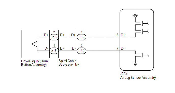
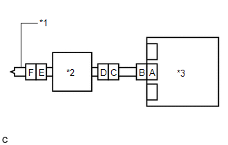
The driver squib circuit consists of the airbag sensor assembly, spiral cable sub-assembly and horn button assembly.
The airbag sensor assembly uses this circuit to deploy the airbag when deployment conditions are met.
These DTCs are stored when a malfunction is detected in the driver squib circuit.
| DTC No. | Detection Item | DTC Detection Condition | Trouble Area | Warning Indicate | Test Mode / Check Mode |
|---|---|---|---|---|---|
| B1800 | Short in D Squib Circuit |
|
| Comes on | Applies to check mode |
| B1801 | Open in D Squib Circuit |
|
| Comes on | Applies to check mode |
| B1802 | Short in D Squib Circuit (to Ground) |
|
| Comes on | Applies to check mode |
| B1803 | Short in D Squib Circuit (to +B) |
|
| Comes on | Applies to check mode |
WIRING DIAGRAM
CAUTION / NOTICE / HINT
NOTICE:
After turning the engine switch off, waiting time may be required before disconnecting the cable from the negative (-) battery terminal. Therefore, make sure to read the disconnecting the cable from the negative (-) battery terminal notices before proceeding with work.
Click here .gif)
HINT:
-
Perform the simulation method by selecting check mode (Signal Check) using the Techstream.
Click here
-
After selecting check mode (Signal Check), perform the simulation method by wiggling each connector of the airbag system or driving the vehicle on a city road or rough road.
Click here
PROCEDURE
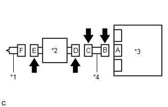
| 1. | CHECK CONNECTORS |
| (a) Turn the engine switch off. |
|
(b) Disconnect the cable from the negative (-) battery terminal.
CAUTION:
Wait at least 90 seconds after disconnecting the cable from the negative (-) battery terminal to disable the SRS system.
(c) Check that the connectors are properly connected to the horn button assembly, spiral cable sub-assembly and airbag sensor assembly.
OK:
The connectors are properly connected.
HINT:
If the connectors are not properly connected, reconnect the connectors and proceed to the next inspection.
(d) Disconnect the connectors from the horn button assembly, spiral cable sub-assembly and airbag sensor assembly.
(e) Check that the terminals of the connectors are not deformed or damaged.
OK:
The terminals are not deformed or damaged.
(f) Check that the spiral cable sub-assembly connector (on the horn button assembly side) is not loose, deformed or damaged.
OK:
The airbag connector locking button is not disengaged, and the claw of the lock is not deformed or damaged.
(g) Check that the short springs of the activation prevention mechanisms of the instrument panel wire connector and spiral cable sub-assembly connector are not deformed or damaged.
OK:
The short springs are not deformed or damaged.
| NG | .gif) | REPLACE WIRE HARNESS |
|
.gif)
| 2. | CHECK HORN BUTTON ASSEMBLY |
| (a) Connect the instrument panel wire to the airbag sensor assembly and spiral cable sub-assembly. |
|
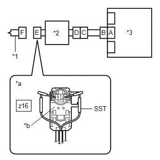
(b) Connect SST (resistance 2.1 Ω) to connector E (light green connector).
CAUTION:
Never connect a tester to the horn button assembly for measurement, as this may lead to a serious injury due to airbag deployment.
NOTICE:
- Do not forcibly insert SST into the terminals of the connector when connecting it.
- Insert SST straight into the terminals of the connector.
SST: 09843-18061
(c) Connect the cable to the negative (-) battery terminal.
(d) Turn the engine switch on (IG), and wait for at least 60 seconds.
(e) Clear the DTCs stored in memory.
Body Electrical > SRS Airbag > Clear DTCs(f) Turn the engine switch off.
(g) Turn the engine switch on (IG), and wait for at least 60 seconds.
(h) Check for DTCs.
Body Electrical > SRS Airbag > Trouble CodesOK:
DTC B1800, B1801, B1802 or B1803 is not output.
HINT:
Codes other than DTCs B1800, B1801, B1802 and B1803 may be output at this time, but they are not related to this check.
(i) Turn the engine switch off.
(j) Disconnect the cable from the negative (-) battery terminal.
CAUTION:
Wait at least 90 seconds after disconnecting the cable from the negative (-) battery terminal to disable the SRS system.
(k) Disconnect SST from connector E.
| OK | | REPLACE HORN BUTTON ASSEMBLY |
|
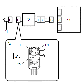
| 3. | CHECK DRIVER SQUIB CIRCUIT |
| (a) Disconnect the instrument panel wire from the airbag sensor assembly. |
|
(b) Check for a short to B+ in the circuit.
(1) Connect the cable to the negative (-) battery terminal.
(2) Turn the engine switch on (IG).
(3) Measure the voltage according to the value(s) in the table below.
Standard Voltage:
| Tester Connection | Condition | Specified Condition |
|---|---|---|
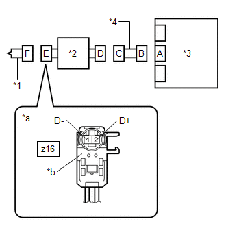
| z16-2 (D+) - Body ground | Engine switch on (IG) | Below 1 V |
| z16-1 (D-) - Body ground | Engine switch on (IG) | Below 1 V |
(4) Turn the engine switch off.
(5) Disconnect the cable from the negative (-) battery terminal.
CAUTION:
Wait at least 90 seconds after disconnecting the cable from the negative (-) battery terminal to disable the SRS system.
(c) Check for an open in the circuit.
(1) Measure the resistance according to the value(s) in the table below.
Standard Resistance:
| Tester Connection | Condition | Specified Condition |
|---|---|---|
| z16-2 (D+) - z16-1 (D-) | Always | Below 1 Ω |
(d) Check for a short to ground in the circuit.
(1) Measure the resistance according to the value(s) in the table below.
Standard Resistance:
| Tester Connection | Condition | Specified Condition |
|---|---|---|
| z16-2 (D+) - Body ground | Always | 1 MΩ or higher |
| z16-1 (D-) - Body ground | Always | 1 MΩ or higher |
(e) Check for a short in the circuit.
(1) Release the activation prevention mechanism built into connector B.
Click here
(2) Measure the resistance according to the value(s) in the table below.
Standard Resistance:
| Tester Connection | Condition | Specified Condition |
|---|---|---|
| z16-2 (D+) - z16-1 (D-) | Always | 1 MΩ or higher |
(3) Restore the released activation prevention mechanism of connector B to the original condition.
| NG | | GO TO STEP 5 |
|
| 4. | CHECK DTC |
| (a) Connect the connectors to the horn button assembly and airbag sensor assembly. |
|
(b) Connect the cable to the negative (-) battery terminal.
(c) Turn the engine switch on (IG), and wait for at least 60 seconds.
(d) Clear the DTCs stored in memory.
Body Electrical > SRS Airbag > Clear DTCs(e) Turn the engine switch off.
(f) Turn the engine switch on (IG), and wait for at least 60 seconds.
(g) Check for DTCs.
Body Electrical > SRS Airbag > Trouble CodesOK:
DTC B1800, B1801, B1802 or B1803 is not output.
HINT:
Codes other than DTCs B1800, B1801, B1802 and B1803 may be output at this time, but they are not related to this check.
| OK | | USE SIMULATION METHOD TO CHECK |
| NG | | REPLACE AIRBAG SENSOR ASSEMBLY |
| 5. | CHECK INSTRUMENT PANEL WIRE |
| (a) Disconnect the instrument panel wire from the spiral cable sub-assembly. |
|
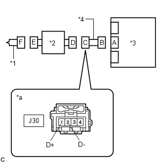
(b) Check for a short to B+ in the circuit.
(1) Connect the cable to the negative (-) battery terminal.
(2) Turn the engine switch on (IG).
(3) Measure the voltage according to the value(s) in the table below.
Standard Voltage:
| Tester Connection | Condition | Specified Condition |
|---|---|---|
| J30-1 (D+) - Body ground | Engine switch on (IG) | Below 1 V |
| J30-2 (D-) - Body ground | Engine switch on (IG) | Below 1 V |
(4) Turn the engine switch off.
(5) Disconnect the cable from the negative (-) battery terminal.
CAUTION:
Wait at least 90 seconds after disconnecting the cable from the negative (-) battery terminal to disable the SRS system.
(c) Check for an open in the circuit.
(1) Measure the resistance according to the value(s) in the table below.
Standard Resistance:
| Tester Connection | Condition | Specified Condition |
|---|---|---|
| J30-1 (D+) - J30-2 (D-) | Always | Below 1 Ω |
(d) Check for a short to ground in the circuit.
(1) Measure the resistance according to the value(s) in the table below.
Standard Resistance:
| Tester Connection | Condition | Specified Condition |
|---|---|---|
| J30-1 (D+) - Body ground | Always | 1 MΩ or higher |
| J30-2 (D-) - Body ground | Always | 1 MΩ or higher |
(e) Check for a short in the circuit.
(1) Release the activation prevention mechanism built into connector B.
Click here
(2) Measure the resistance according to the value(s) in the table below.
Standard Resistance:
| Tester Connection | Condition | Specified Condition |
|---|---|---|
| J30-1 (D+) - J30-2 (D-) | Always | 1 MΩ or higher |
(3) Restore the released activation prevention mechanism of connector B to the original condition.
| NG | | REPLACE INSTRUMENT PANEL WIRE |
|
| 6. | CHECK SPIRAL CABLE SUB-ASSEMBLY |
| (a) Check for a short to B+ in the circuit. (1) Connect the cable to the negative (-) battery terminal. (2) Turn the engine switch on (IG). (3) Measure the voltage according to the value(s) in the table below. Standard Voltage:
(4) Turn the engine switch off. (5) Disconnect the cable from the negative (-) battery terminal. CAUTION: Wait at least 90 seconds after disconnecting the cable from the negative (-) battery terminal to disable the SRS system. |
|
(b) Check for an open in the circuit.
(1) Measure the resistance according to the value(s) in the table below.
Standard Resistance:
| Tester Connection | Condition | Specified Condition |
|---|---|---|
| z16-2 (D+) - z16-1 (D-) | Always | Below 1 Ω |
(c) Check for a short to ground in the circuit.
(1) Measure the resistance according to the value(s) in the table below.
Standard Resistance:
| Tester Connection | Condition | Specified Condition |
|---|---|---|
| z16-2 (D+) - Body ground | Always | 1 MΩ or higher |
| z16-1 (D-) - Body ground | Always | 1 MΩ or higher |
(d) Check for a short in the circuit.
(1) Release the activation prevention mechanism built into connector D.
Click here
(2) Measure the resistance according to the value(s) in the table below.
Standard Resistance:
| Tester Connection | Condition | Specified Condition |
|---|---|---|
| z16-2 (D+) - z16-1 (D-) | Always | 1 MΩ or higher |
(3) Restore the released activation prevention mechanism of connector D to the original condition.
| OK | | USE SIMULATION METHOD TO CHECK |
| NG | | REPLACE SPIRAL CABLE SUB-ASSEMBLY |
 Lost Communication with Front Door Pressure Sensor LH (B167B,B167C)
DESCRIPTION The side collision sensor LH circuit (bus 1) consists of the airbag sensor assembly, door side airbag sensor LH and rear airbag sensor LH. The door side airbag sensor LH and rear airbag se ...
 Short in P Squib Circuit (B1805-B1808)
DESCRIPTION The front passenger squib circuit consists of the airbag sensor assembly and instrument panel passenger airbag assembly. The airbag sensor assembly uses this circuit to deploy the airbag w ...
Other materials:
Lexus RX (RX 350L, RX450h) 2016-2026 Owners Manual > Adjusting the steering wheel and mirrors: Outside rear view mirrors
Adjustment procedure
1. To select a mirror to adjust, press the
switch.
Left
Right
Pressing the same switch again will
put the switch in neutral.
2. To adjust the mirror, press the switch.
Up
Right
Down
Left
Folding the mirrors (manual type)
Push the mirror back in the ...
Lexus RX (RX 350L, RX450h) 2016-2026 Repair Manual > Parking Assist Monitor System: Reverse Signal Circuit
DESCRIPTION The multi-display assembly receives a reverse signal from the park/neutral position switch assembly*1 or clearance warning ECU assembly*2. *1: except 12.3 Inch Display and w/ Intuitive Parking Assist System *2: for 12.3 Inch Display and w/ Intuitive Parking Assist System WIRING DIAGRAM ...
Lexus RX (RX 350L, RX450h) 2016-{YEAR} Owners Manual
- For your information
- Pictorial index
- For safety and security
- Instrument cluster
- Operation of each component
- Driving
- Lexus Display Audio system
- Interior features
- Maintenance and care
- When trouble arises
- Vehicle specifications
- For owners
Lexus RX (RX 350L, RX450h) 2016-{YEAR} Repair Manual

0.0113