Lexus RX (RX 350L, RX450h) 2016-2026 Repair Manual: Lost Communication with Front Door Pressure Sensor LH (B167B,B167C)
DESCRIPTION
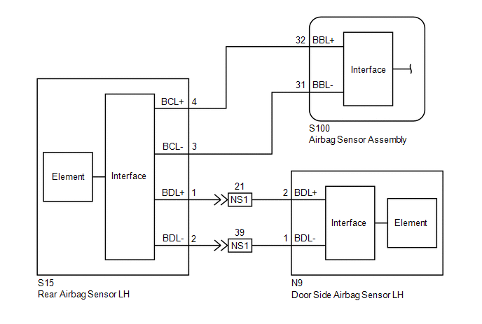
The side collision sensor LH circuit (bus 1) consists of the airbag sensor assembly, door side airbag sensor LH and rear airbag sensor LH.
The door side airbag sensor LH and rear airbag sensor LH detect impacts to the vehicle and send signals to the airbag sensor assembly to determine if the airbags and pretensioners should be deployed.
These DTCs are stored when a malfunction is detected in the side collision sensor LH circuit (bus 1).
| DTC No. | Detection Item | DTC Detection Condition | Trouble Area | Warning Indicate | Test Mode / Check Mode |
|---|---|---|---|---|---|
| B167B | Lost Communication with Front Door Pressure Sensor LH |
|
| Comes on | Does not apply to test/check mode |
| B167C | Front Door Pressure Sensor LH Initialization Incomplete |
|
| Comes on | Does not apply to test/check mode |
WIRING DIAGRAM
CAUTION / NOTICE / HINT
NOTICE:
After turning the engine switch off, waiting time may be required before disconnecting the cable from the negative (-) battery terminal. Therefore, make sure to read the disconnecting the cable from the negative (-) battery terminal notices before proceeding with work.
Click here .gif)
PROCEDURE
| 1. | CHECK CONNECTION OF CONNECTORS |
(a) Turn the engine switch off.
(b) Disconnect the cable from the negative (-) battery terminal.
CAUTION:
Wait at least 90 seconds after disconnecting the cable from the negative (-) battery terminal to disable the SRS system.
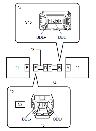
(c) Check that the connectors are properly connected to the door side airbag sensor LH and rear airbag sensor LH. Also check that the connectors that link the No. 2 floor wire and front door wire LH are properly connected.
OK:
The connectors are properly connected.
| NG | .gif) | CONNECT CONNECTORS PROPERLY |
|
.gif)
| 2. | CHECK CONNECTORS |
(a) Disconnect the connectors from the door side airbag sensor LH and rear airbag sensor LH. Also disconnect the connectors that link the No. 2 floor wire and front door wire LH.
(b) Check that the terminals of the connectors are not deformed or damaged.
OK:
The terminals are not deformed or damaged.
| NG | | REPLACE NO. 2 FLOOR WIRE OR FRONT DOOR WIRE LH |
|
| 3. | CHECK WIRE HARNESS |
| (a) Connect the connectors that link the No. 2 floor wire and front door wire LH. |
|
(b) Connect the cable to the negative (-) battery terminal.
(c) Turn the engine switch on (IG).
(d) Measure the voltage according to the value(s) in the table below.
Standard Voltage:
| Tester Connection | Condition | Specified Condition |
|---|---|---|
| S15-1 (BDL+) - Body ground | Engine switch on (IG) | Below 1 V |
| S15-2 (BDL-) - Body ground | Engine switch on (IG) | Below 1 V |
(e) Turn the engine switch off.
(f) Disconnect the cable from the negative (-) battery terminal.
CAUTION:
Wait at least 90 seconds after disconnecting the cable from the negative (-) battery terminal to disable the SRS system.
(g) Using a service wire, connect terminals 2 (BDL+) and 1 (BDL-) of connector E.
NOTICE:
Do not forcibly insert the service wire into the terminals of the connector when connecting the wire.
(h) Measure the resistance according to the value(s) in the table below.
Standard Resistance:
| Tester Connection | Condition | Specified Condition |
|---|---|---|
| S15-1 (BDL+) - S15-2 (BDL-) | Always | Below 1 Ω |
(i) Disconnect the service wire from connector E.
(j) Measure the resistance according to the value(s) in the table below.
Standard Resistance:
| Tester Connection | Condition | Specified Condition |
|---|---|---|
| S15-1 (BDL+) - S15-2 (BDL-) | Always | 1 MΩ or higher |
| S15-1 (BDL+) - Body ground | Always | 1 MΩ or higher |
| S15-2 (BDL-) - Body ground | Always | 1 MΩ or higher |
| NG | | GO TO STEP 6 |
|
| 4. | CHECK REAR AIRBAG SENSOR LH |
| (a) Connect the connector to the door side airbag sensor LH. |
|
.png)
(b) Interchange the rear airbag sensor LH with RH and connect the connectors.
(c) Connect the cable to the negative (-) battery terminal.
(d) Turn the engine switch on (IG), and wait for at least 60 seconds.
(e) Clear the DTCs stored in memory.
Body Electrical > SRS Airbag > Clear DTCs(f) Turn the engine switch off.
(g) Turn the engine switch on (IG), and wait for at least 60 seconds.
(h) Check for DTCs.
Body Electrical > SRS Airbag > Trouble CodesHINT:
Codes other than DTCs B166D, B166E, B167B and B167C may be output at this time, but they are not related to this check.
| Result | Proceed to |
|---|---|
| DTC B167B or B167C is output. | A |
| DTC B166D or B166E is output. | B |
| DTCs B166D, B166E, B167B and B167C are not output. | C |
(i) Turn the engine switch off.
(j) Disconnect the cable from the negative (-) battery terminal.
CAUTION:
Wait at least 90 seconds after disconnecting the cable from the negative (-) battery terminal to disable the SRS system.
(k) Return the rear airbag sensor LH and RH to their original positions and connect the connectors.
| B | | REPLACE REAR AIRBAG SENSOR LH |
| C | | USE SIMULATION METHOD TO CHECK |
|
| 5. | CHECK DOOR SIDE AIRBAG SENSOR LH |
| (a) Interchange the door side airbag sensor LH with RH and connect the connectors. |
|
(b) Connect the cable to the negative (-) battery terminal.
(c) Turn the engine switch on (IG), and wait for at least 60 seconds.
(d) Clear the DTCs stored in memory.
Body Electrical > SRS Airbag > Clear DTCs(e) Turn the engine switch off.
(f) Turn the engine switch on (IG), and wait for at least 60 seconds.
(g) Check for DTCs.
Body Electrical > SRS Airbag > Trouble CodesHINT:
Codes other than DTCs B166D, B166E, B167B and B167C may be output at this time, but they are not related to this check.
| Result | Proceed to |
|---|---|
| DTC B167B or B167C is output. | A |
| DTC B166D or B166E is output. | B |
| DTCs B166D, B166E, B167B and B167C are not output. | C |
(h) Turn the engine switch off.
(i) Disconnect the cable from the negative (-) battery terminal.
CAUTION:
Wait at least 90 seconds after disconnecting the cable from the negative (-) battery terminal to disable the SRS system.
(j) Return the door side airbag sensor LH and RH to their original positions and connect the connectors.
| A | | REPLACE AIRBAG SENSOR ASSEMBLY |
| B | | REPLACE DOOR SIDE AIRBAG SENSOR LH |
| C | | USE SIMULATION METHOD TO CHECK |
| 6. | CHECK NO. 2 FLOOR WIRE |
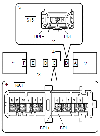
| (a) Disconnect the No. 2 floor wire connector from the front door wire LH. |
|
(b) Connect the cable to the negative (-) battery terminal.
(c) Turn the engine switch on (IG).
(d) Measure the voltage according to the value(s) in the table below.
Standard Voltage:
| Tester Connection | Condition | Specified Condition |
|---|---|---|
| NS1-21 (BDL+) - Body ground | Engine switch on (IG) | Below 1 V |
| NS1-39 (BDL-) - Body ground | Engine switch on (IG) | Below 1 V |
(e) Turn the engine switch off.
(f) Disconnect the cable from the negative (-) battery terminal.
CAUTION:
Wait at least 90 seconds after disconnecting the cable from the negative (-) battery terminal to disable the SRS system.
(g) Using a service wire, connect terminals 1 (BDL+) and 2 (BDL-) of connector B.
NOTICE:
Do not forcibly insert the service wire into the terminals of the connector when connecting the wire.
(h) Measure the resistance according to the value(s) in the table below.
Standard Resistance:
| Tester Connection | Condition | Specified Condition |
|---|---|---|
| NS1-21 (BDL+) - NS1-39 (BDL-) | Always | Below 1 Ω |
(i) Disconnect the service wire from connector B.
(j) Measure the resistance according to the value(s) in the table below.
Standard Resistance:
| Tester Connection | Condition | Specified Condition |
|---|---|---|
| NS1-21 (BDL+) - NS1-39 (BDL-) | Always | 1 MΩ or higher |
| NS1-21 (BDL+) - Body ground | Always | 1 MΩ or higher |
| NS1-39 (BDL-) - Body ground | Always | 1 MΩ or higher |
| OK | | REPLACE FRONT DOOR WIRE LH |
| NG | | REPLACE NO. 2 FLOOR WIRE |
 Front Door Pressure Sensor LH (B167A,B167E)
DESCRIPTION The side collision sensor LH circuit (bus 1) consists of the airbag sensor assembly, door side airbag sensor LH and rear airbag sensor LH. The door side airbag sensor LH and rear airbag se ...
 Short in D Squib Circuit (B1800-B1803)
DESCRIPTION The driver squib circuit consists of the airbag sensor assembly, spiral cable sub-assembly and horn button assembly. The airbag sensor assembly uses this circuit to deploy the airbag when ...
Other materials:
Lexus RX (RX 350L, RX450h) 2016-2026 Repair Manual > Vehicle Stability Control System: ABS Pump Motor Control Circuit Voltage Out of Range (C052C1C)
DESCRIPTION DTC No. Detection Item DTC Detection Condition Trouble Area C052C1C ABS Pump Motor Control Circuit Voltage Out of Range When the +BS terminal voltage is from 9.5 to 17.4 V with the motor relay and motor fail safe relay OFF, an open or short in motor circuit continues for ...
Lexus RX (RX 350L, RX450h) 2016-2026 Repair Manual > Washer Nozzle(for Rear Side): On-vehicle Inspection
ON-VEHICLE INSPECTION PROCEDURE 1. INSPECT REAR WASHER NOZZLE (w/o Rear No. 2 Seat) (a) Operate the rear washer nozzle and check the position that the washer fluid contacts the back door glass. Standard: Washer fluid contacts the back door glass in the area shown in the illustration. *a Cente ...
Lexus RX (RX 350L, RX450h) 2016-{YEAR} Owners Manual
- For your information
- Pictorial index
- For safety and security
- Instrument cluster
- Operation of each component
- Driving
- Lexus Display Audio system
- Interior features
- Maintenance and care
- When trouble arises
- Vehicle specifications
- For owners
Lexus RX (RX 350L, RX450h) 2016-{YEAR} Repair Manual

0.0096