Lexus RX (RX 350L, RX450h) 2016-2026 Repair Manual: Short in Side Squib (RH) Circuit (B1820-B1823)
DESCRIPTION
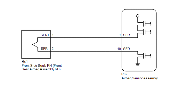
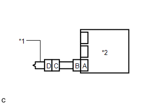
The front side squib RH circuit consists of the airbag sensor assembly and front seat airbag assembly RH.
The airbag sensor assembly uses this circuit to deploy the airbag when deployment conditions are met.
These DTCs are stored when a malfunction is detected in the front side squib RH circuit.
| DTC No. | Detection Item | DTC Detection Condition | Trouble Area | Warning Indicate | Test Mode / Check Mode |
|---|---|---|---|---|---|
| B1820 | Short in Side Squib (RH) Circuit |
|
| Comes on | Applies to check mode |
| B1821 | Open in Side Squib (RH) Circuit |
|
| Comes on | Applies to check mode |
| B1822 | Short in Side Squib (RH) Circuit (to Ground) |
|
| Comes on | Applies to check mode |
| B1823 | Short in Side Squib (RH) Circuit (to +B) |
|
| Comes on | Applies to check mode |
WIRING DIAGRAM
CAUTION / NOTICE / HINT
NOTICE:
After turning the engine switch off, waiting time may be required before disconnecting the cable from the negative (-) battery terminal. Therefore, make sure to read the disconnecting the cable from the negative (-) battery terminal notices before proceeding with work.
Click here .gif)
HINT:
-
Perform the simulation method by selecting check mode (Signal Check) using the Techstream.
Click here
-
After selecting check mode (Signal Check), perform the simulation method by wiggling each connector of the airbag system or driving the vehicle on a city road or rough road.
Click here
PROCEDURE
| 1. | CHECK CONNECTORS |
| (a) Turn the engine switch off. |
|
(b) Disconnect the cable from the negative (-) battery terminal.
CAUTION:
Wait at least 90 seconds after disconnecting the cable from the negative (-) battery terminal to disable the SRS system.
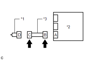
(c) Check that the connectors are properly connected to the front seat airbag assembly RH and airbag sensor assembly.
OK:
The connectors are properly connected.
HINT:
If the connectors are not properly connected, reconnect the connectors and proceed to the next inspection.
(d) Disconnect the connectors from the front seat airbag assembly RH and airbag sensor assembly.
(e) Check that the terminals of the connectors are not deformed or damaged.
OK:
The terminals are not deformed or damaged.
(f) Check that the short springs of the activation prevention mechanism of the floor wire connector are not deformed or damaged.
OK:
The short springs are not deformed or damaged.
| NG | .gif) | REPLACE FLOOR WIRE |
|
.gif)
| 2. | CHECK FRONT SEAT AIRBAG ASSEMBLY RH |
| (a) Connect the connector to the airbag sensor assembly. |
|
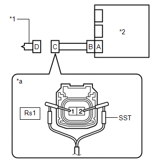
(b) Connect SST (resistance 2.1 Ω) to connector C.
CAUTION:
Never connect a tester to the front seat airbag assembly RH for measurement, as this may lead to a serious injury due to airbag deployment.
NOTICE:
- Do not forcibly insert SST into the terminals of the connector when connecting it.
- Insert SST straight into the terminals of the connector.
SST: 09843-18061
(c) Connect the cable to the negative (-) battery terminal.
(d) Turn the engine switch on (IG), and wait for at least 60 seconds.
(e) Clear the DTCs stored in memory.
Body Electrical > SRS Airbag > Clear DTCs(f) Turn the engine switch off.
(g) Turn the engine switch on (IG), and wait for at least 60 seconds.
(h) Check for DTCs.
Body Electrical > SRS Airbag > Trouble CodesOK:
DTC B1820, B1821, B1822 or B1823 is not output.
HINT:
Codes other than DTCs B1820, B1821, B1822 and B1823 may be output at this time, but they are not related to this check.
(i) Turn the engine switch off.
(j) Disconnect the cable from the negative (-) battery terminal.
CAUTION:
Wait at least 90 seconds after disconnecting the cable from the negative (-) battery terminal to disable the SRS system.
(k) Disconnect SST from connector C.
| OK | | REPLACE FRONT SEAT AIRBAG ASSEMBLY RH |
|
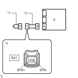
| 3. | CHECK FLOOR WIRE |
| (a) Disconnect the floor wire from the airbag sensor assembly. |
|
(b) Check for a short to B+ in the circuit.
(1) Connect the cable to the negative (-) battery terminal.
(2) Turn the engine switch on (IG).
(3) Measure the voltage according to the value(s) in the table below.
Standard Voltage:
| Tester Connection | Condition | Specified Condition |
|---|---|---|
| Rs1-1 (SFR+) - Body ground | Engine switch on (IG) | Below 1 V |
| Rs1-2 (SFR-) - Body ground | Engine switch on (IG) | Below 1 V |
(4) Turn the engine switch off.
(5) Disconnect the cable from the negative (-) battery terminal.
CAUTION:
Wait at least 90 seconds after disconnecting the cable from the negative (-) battery terminal to disable the SRS system.
(c) Check for an open in the circuit.
(1) Measure the resistance according to the value(s) in the table below.
Standard Resistance:
| Tester Connection | Condition | Specified Condition |
|---|---|---|
| Rs1-1 (SFR+) - Rs1-2 (SFR-) | Always | Below 1 Ω |
(d) Check for a short to ground in the circuit.
(1) Measure the resistance according to the value(s) in the table below.
Standard Resistance:
| Tester Connection | Condition | Specified Condition |
|---|---|---|
| Rs1-1 (SFR+) - Body ground | Always | 1 MΩ or higher |
| Rs1-2 (SFR-) - Body ground | Always | 1 MΩ or higher |
(e) Check for a short in the circuit.
(1) Release the activation prevention mechanism built into connector B.
Click here
(2) Measure the resistance according to the value(s) in the table below.
Standard Resistance:
| Tester Connection | Condition | Specified Condition |
|---|---|---|
| Rs1-1 (SFR+) - Rs1-2 (SFR-) | Always | 1 MΩ or higher |
(3) Restore the released activation prevention mechanism of connector B to the original condition.
| NG | | REPLACE FLOOR WIRE |
|
| 4. | CHECK DTC |
| (a) Connect the connectors to the front seat airbag assembly RH and airbag sensor assembly. |
|
(b) Connect the cable to the negative (-) battery terminal.
(c) Turn the engine switch on (IG), and wait for at least 60 seconds.
(d) Clear the DTCs stored in memory.
Body Electrical > SRS Airbag > Clear DTCs(e) Turn the engine switch off.
(f) Turn the engine switch on (IG), and wait for at least 60 seconds.
(g) Check for DTCs.
Body Electrical > SRS Airbag > Trouble CodesOK:
DTC B1820, B1821, B1822 or B1823 is not output.
HINT:
Codes other than DTCs B1820, B1821, B1822 and B1823 may be output at this time, but they are not related to this check.
| OK | | USE SIMULATION METHOD TO CHECK |
| NG | | REPLACE AIRBAG SENSOR ASSEMBLY |
 Short in P Squib (Dual Stage - 2nd Step) Circuit (B1815-B1818)
DESCRIPTION The front passenger squib 2nd step circuit consists of the airbag sensor assembly and instrument panel passenger airbag assembly. The airbag sensor assembly uses this circuit to deploy the ...
 Short in Side Squib (LH) Circuit (B1825-B1828)
DESCRIPTION The front side squib LH circuit consists of the airbag sensor assembly and front seat airbag assembly LH. The airbag sensor assembly uses this circuit to deploy the airbag when deployment ...
Other materials:
Lexus RX (RX 350L, RX450h) 2016-2026 Repair Manual > Navigation System: Panel Switches do not Function
CAUTION / NOTICE / HINT NOTICE: Depending on the parts that are replaced during vehicle inspection or maintenance, performing initialization, registration or calibration may be needed. Refer to Precaution for Navigation System. Click here PROCEDURE 1. CHECK PANEL SWITCH (a) Check for fore ...
Lexus RX (RX 350L, RX450h) 2016-2026 Repair Manual > Towing Converter System: System Description
SYSTEM DESCRIPTION INPUT SIGNAL Item Detail Stop lights Receives a stop light signal from the stop light switch via direct line. Turn indicator lights Receives turn indicator light signals from the turn signal flasher via direct line. Taillights Receives a taillight signal fro ...
Lexus RX (RX 350L, RX450h) 2016-{YEAR} Owners Manual
- For your information
- Pictorial index
- For safety and security
- Instrument cluster
- Operation of each component
- Driving
- Lexus Display Audio system
- Interior features
- Maintenance and care
- When trouble arises
- Vehicle specifications
- For owners
Lexus RX (RX 350L, RX450h) 2016-{YEAR} Repair Manual

0.0128