Lexus RX (RX 350L, RX450h) 2016-2026 Repair Manual: Removal
REMOVAL
CAUTION / NOTICE / HINT
The necessary procedures (adjustment, calibration, initialization, or registration) that must be performed after parts are removed and installed, or replaced during radio setting condenser removal/installation are shown below.
Necessary Procedures After Parts Removed/Installed/Replaced| Replaced Part or Performed Procedure | Necessary Procedure | Effect/Inoperative Function when Necessary Procedure not Performed | Link |
|---|---|---|---|
| Disconnect cable from negative battery terminal | Memorize steering angle neutral point | Lane Control System | |
| Pre-collision System | |||
| Intelligent Clearance Sonar System*1 | |||
| Parking Assist Monitor System | | ||
| Panoramic View Monitor System | | ||
| Lighting System (w/ Automatic Headlight Beam Level Control System) | | ||
| Initialize back door lock | Power Door Lock Control System | | |
| Reset back door close position | Power Back Door System (w/ Outside Door Control Switch) | |
*1: When performing learning using the Techstream.
Click here .gif)
CAUTION:
Some of these service operations affect the SRS airbag system. Read the precautionary notices concerning the SRS airbag system before servicing.
Click here
.png)
PROCEDURE
1. REMOVE TONNEAU COVER ASSEMBLY
Click here
2. REMOVE DECK BOARD ASSEMBLY
Click here
3. REMOVE REAR NO. 3 FLOOR BOARD
Click here
4. REMOVE REAR DECK FLOOR BOX
Click here
5. REMOVE REAR NO. 4 FLOOR BOARD
Click here
6. REMOVE FRONT DECK FLOOR BOX
Click here
7. REMOVE DECK SIDE TRIM BOX RH
Click here
8. REMOVE REAR FLOOR FINISH PLATE
Click here
9. REMOVE REAR DOOR SCUFF PLATE LH
Click here
10. REMOVE REAR SEAT ASSEMBLY LH
Click here
11. REMOVE UPPER QUARTER TRIM PAD LH
Click here
12. REMOVE REAR SEAT SIDE GARNISH LH
Click here
13. REMOVE REAR FLOOR FINISH SIDE PLATE LH
Click here
14. REMOVE NO. 1 LUGGAGE COMPARTMENT TRIM HOOK
Click here
15. REMOVE ROPE HOOK ASSEMBLY
Click here
16. REMOVE NO. 1 LUGGAGE COMPARTMENT LIGHT ASSEMBLY
Click here
17. REMOVE DECK TRIM SIDE PANEL ASSEMBLY LH
Click here
18. REMOVE RADIO SETTING CONDENSER
NOTICE:
When the terminal cover is removed, the radio setting condenser must be replaced because the terminal cover and condenser are supplied as a set.
| (a) Remove the bolt. |
|
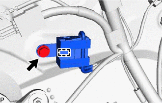
(b) Disengage the clamp and disconnect the radio setting condenser with wire harness from the vehicle body.
| (c) Using a screwdriver, disengage the 3 claws and remove the terminal cover with wire harness from the condenser. |
|
.png)
| (d) Using a screwdriver, bend back and break off the claw as shown in the illustration. |
|
.png)
(e) Remove the terminal cover from the wire harness.
NOTICE:
- Make sure to hold the crimping side of the terminal when disconnecting the wire harness from the terminal cover.
- Make sure not to bend the exposed wire when disconnecting the wire harness from the terminal cover.
- Check for deformation of the terminal after the wire harness has been removed from the terminal cover.
 On-vehicle Inspection
ON-VEHICLE INSPECTION PROCEDURE 1. INSPECT RADIO SETTING CONDENSER (a) With the radio setting condenser installed, check that there is no looseness or other abnormalities. (b) Measure the resistanc ...
 Installation
INSTALLATION PROCEDURE 1. INSTALL RADIO SETTING CONDENSER (a) Engage the claw to install a new terminal cover to the wire harness. NOTICE:
Make sure to hold the crimping side of the terminal w ...
Other materials:
Lexus RX (RX 350L, RX450h) 2016-2026 Repair Manual > Center Airbag Sensor Assembly: On-vehicle Inspection
ON-VEHICLE INSPECTION CAUTION / NOTICE / HINT CAUTION: Be sure to correctly follow the removal and installation procedures for the airbag sensor assembly. PROCEDURE 1. INSPECT AIRBAG SENSOR ASSEMBLY (for Vehicle not Involved in Collision) (a) Perform a diagnostic system check. Click here 2. INSPE ...
Lexus RX (RX 350L, RX450h) 2016-2026 Repair Manual > Panoramic Moon Roof System: Position Initialization Incomplete (B2343)
DESCRIPTION This DTC is stored when the sliding roof ECU (sliding roof drive gear assembly) or roof sunshade ECU (sliding roof drive gear assembly) has not been initialized. Sliding Roof DTC No. Detection Item DTC Detection Condition Trouble Area B2343 Position Initialization Incomple ...
Lexus RX (RX 350L, RX450h) 2016-{YEAR} Owners Manual
- For your information
- Pictorial index
- For safety and security
- Instrument cluster
- Operation of each component
- Driving
- Lexus Display Audio system
- Interior features
- Maintenance and care
- When trouble arises
- Vehicle specifications
- For owners
Lexus RX (RX 350L, RX450h) 2016-{YEAR} Repair Manual

0.0109