Lexus RX (RX 350L, RX450h) 2016-2026 Repair Manual: Removal
REMOVAL
CAUTION / NOTICE / HINT
The necessary procedures (adjustment, calibration, initialization, or registration) that must be performed after parts are removed, installed, or replaced during the instrument panel passenger airbag assembly removal/installation are shown below.
Necessary Procedure After Parts Removed/Installed/Replaced| Replacement Part or Procedure | Necessary Procedures | Effects / Inoperative when not performed | Link |
|---|---|---|---|
| Removal/installation of the spiral cable with sensor sub-assembly |
| Parking assist monitor system | |
| Steering angle neutral point (Initialize panoramic view monitor system) | Panoramic view monitor system | | |
| Steering angle neutral point (Initialize intelligent clearance sonar system) | Intelligent clearance sonar system | | |
| Disconnect cable from negative battery terminal | Memorize steering angle neutral point | Lane control system | |
| Pre-collision system | |||
| Intelligent clearance sonar system*1 | |||
| Lighting system (w/ Automatic Headlight Beam Level Control System) | | ||
| Parking assist monitor system | | ||
| Panoramic view monitor system | | ||
| Initialize back door lock | Power door lock control system | | |
| Reset back door close position | Power back door system | |
*1: When performing learning using the Techstream.
Click here .gif)
PROCEDURE
1. PRECAUTION
CAUTION:
Be sure to read Precaution thoroughly before servicing.
Click here
.png)
NOTICE:
After turning the engine switch off, waiting time may be required before disconnecting the cable from the negative (-) battery terminal. Therefore, make sure to read the disconnecting the cable from the negative (-) battery terminal notices before proceeding with work.
Click here
2. REMOVE FRONT NO. 2 CONSOLE BOX INSERT
Click here
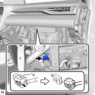
3. DISCONNECT NO. 2 INSTRUMENT PANEL WIRE
(a) Check that the engine switch is off.
(b) Check that the cable is disconnected from the negative (-) battery terminal.
CAUTION:
Wait at least 90 seconds after disconnecting the cable from the negative (-) battery terminal to disable the SRS system.
.png)
| (c) Slide the slider to release the lock, and then disconnect the connector. NOTICE: When disconnecting any airbag connector, take care not to damage the airbag wire harness. |
|
4. REMOVE INSTRUMENT PANEL SAFETY PAD SUB-ASSEMBLY
Click here
5. REMOVE INSTRUMENT PANEL PASSENGER AIRBAG ASSEMBLY
CAUTION:
When storing the instrument panel passenger airbag assembly, keep the airbag deployment side facing upward.
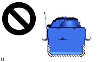
.png) | Deployment Side |
| (a) Remove the 2 screws. |
|
.png)
| (b) Lean the instrument panel safety pad sub-assembly and disengage the 3 hooks. |
|
.png)
| (c) Disengage the 3 hooks to remove the instrument panel passenger airbag assembly from the instrument panel safety pad sub-assembly. |
|
.png)
6. REMOVE NO. 2 INSTRUMENT PANEL WIRE
(a) Disengage the clamp.
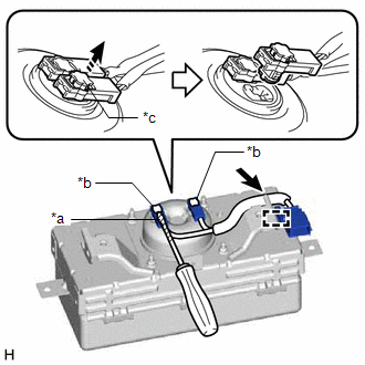
| *a | Protective Tape |
| *b | Airbag Connector |
| *c | Airbag Connector Lock |
.png) | Wire Harness Clamp |
(b) Separate the No. 2 instrument panel wire from the wire harness clamp.
(c) Using a screwdriver with its tip wrapped with protective tape, release the 2 airbag connector locks.
(d) Disconnect the 2 airbag connectors to remove the No. 2 instrument panel wire from the instrument panel passenger airbag assembly.
NOTICE:
When disconnecting any airbag connector, take care not to damage the airbag wire harness.
 Installation
INSTALLATION PROCEDURE 1. INSTALL NO. 2 INSTRUMENT PANEL WIRE (a) Connect the 2 airbag connectors of the No. 2 instrument panel wire to the instrument panel passenger airbag assembly. *a Airbag ...
 Disposal
DISPOSAL CAUTION / NOTICE / HINT CAUTION: Before performing pre-disposal deployment of any SRS part, review and closely follow all applicable environmental and hazardous material regulations. Pre-disp ...
Other materials:
Lexus RX (RX 350L, RX450h) 2016-2026 Repair Manual > Seat Heater Switch (for Front Side): Components
COMPONENTS ILLUSTRATION *1 CONSOLE PANEL SUB-ASSEMBLY *2 INSTRUMENT CLUSTER FINISH PANEL ORNAMENT *3 LOWER NO. 1 INSTRUMENT PANEL FINISH PANEL *4 LOWER NO. 2 INSTRUMENT PANEL FINISH PANEL *5 REAR CONSOLE UPPER PANEL *6 REFRESHING SEAT SWITCH *7 SHIFT LEVER KNOB SU ...
Lexus RX (RX 350L, RX450h) 2016-2026 Repair Manual > Can Communication System: ECM Communication Stop Mode
DESCRIPTION Detection Item Symptom Trouble Area ECM Communication Stop Mode Either condition is met:
"ECM (Engine)" is not displayed on the CAN Bus Check screen of the Techstream.
Click here
Communication system DTCs (DTCs that start with U) that correspond to "ECM Communicati ...
Lexus RX (RX 350L, RX450h) 2016-{YEAR} Owners Manual
- For your information
- Pictorial index
- For safety and security
- Instrument cluster
- Operation of each component
- Driving
- Lexus Display Audio system
- Interior features
- Maintenance and care
- When trouble arises
- Vehicle specifications
- For owners
Lexus RX (RX 350L, RX450h) 2016-{YEAR} Repair Manual

0.0237