Lexus RX (RX 350L, RX450h) 2016-2026 Repair Manual: Passenger Side Buckle Switch Circuit Malfunction (B1771)
DESCRIPTION
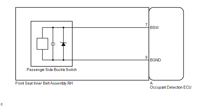
The passenger side buckle switch circuit consists of the occupant detection ECU and passenger side buckle switch (front seat inner belt assembly RH).
DTC B1771 is stored when a malfunction is detected in the passenger side buckle switch circuit.
| DTC No. | Detection Item | DTC Detection Condition | Trouble Area |
|---|---|---|---|
| B1771 | Passenger Side Buckle Switch Circuit Malfunction |
|
|
WIRING DIAGRAM
CAUTION / NOTICE / HINT
NOTICE:
After turning the engine switch off, waiting time may be required before disconnecting the cable from the negative (-) battery terminal. Therefore, make sure to read the disconnecting the cable from the negative (-) battery terminal notices before proceeding with work.
Click here .gif)
HINT:
- When DTC B1650 is stored as a result of troubleshooting for the airbag system, check the DTCs stored in the occupant detection ECU. When DTC B1771 is output, perform troubleshooting for this DTC first.
- If it is difficult to perform troubleshooting (wire harness inspection), remove the front passenger seat installation bolts to see under the seat cushion.
- In the above case, lift and hold the seat so that it does not fall down. Hold the seat only as necessary because holding the seat for a long period of time may cause seat rail deformation.
PROCEDURE
| 1. | CHECK CONNECTORS |
(a) Turn the engine switch off.
(b) Disconnect the cable from the negative (-) battery terminal.
(c) Check that the connector is properly connected to the occupant detection ECU.
OK:
The connector is properly connected.
HINT:
If the connector is not properly connected, reconnect the connector and proceed to the next inspection.
(d) Disconnect the connector from the occupant detection ECU.
(e) Check that the terminals of the connector are not deformed or damaged.
OK:
The terminals are not deformed or damaged.
| NG | .gif) | REPLACE FRONT SEAT INNER BELT ASSEMBLY RH |
|
.gif)
| 2. | CHECK DTC |
(a) Connect the connector to the occupant detection ECU.
(b) Connect the cable to the negative (-) battery terminal.
(c) Clear the DTCs stored in the occupant detection ECU.
Click here
(d) Clear the DTCs stored in the airbag sensor assembly.
Click here
(e) Turn the engine switch off.
(f) Turn the engine switch on (IG), and wait for at least 10 seconds.
(g) Check for DTCs.
Click here
OK:
DTC B1771 is not output.
HINT:
Codes other than DTC B1771 may be output at this time, but they are not related to this check.
(h) Turn the engine switch off.
| OK | | USE SIMULATION METHOD TO CHECK |
|
| 3. | CHECK FRONT SEAT INNER BELT ASSEMBLY RH |
(a) Disconnect the cable from the negative (-) battery terminal.
(b) Replace the front seat inner belt assembly RH with a known good one.
Click here
HINT:
Perform the following inspection using known good parts from another vehicle if possible.
(c) Connect the cable to the negative (-) battery terminal.
(d) Clear the DTCs stored in the occupant detection ECU.
Click here
(e) Clear the DTCs stored in the airbag sensor assembly.
Click here
(f) Turn the engine switch off.
(g) Turn the engine switch on (IG), and wait for at least 10 seconds.
(h) Check for DTCs.
Click here
OK:
DTC B1771 is not output.
HINT:
Codes other than DTC B1771 may be output at this time, but they are not related to this check.
(i) Turn the engine switch off.
(j) Disconnect the cable from the negative (-) battery terminal.
(k) Restore the front seat inner belt assembly RH that was installed for testing to its original location.
Click here
| OK | | REPLACE FRONT SEAT INNER BELT ASSEMBLY RH |
|
| 4. | REPLACE OCCUPANT DETECTION ECU |
(a) Turn the engine switch off.
(b) Disconnect the cable from the negative (-) battery terminal.
(c) Replace the occupant detection ECU with a new one.
Click here
(d) Connect the cable to the negative (-) battery terminal.
|
| 5. | PERFORM ZERO POINT CALIBRATION |
(a) Using the Techstream, perform Zero Point Calibration.
Click here
| Tester Display |
|---|
| Zero Point Calibration |
| NEXT | | END |
 Data List / Active Test
DATA LIST / ACTIVE TEST DATA LIST HINT: Using the Techstream to read the Data List allows the values or states of switches, sensors, actuators and other items to be read without removing any parts. Th ...
 Front Occupant Classification Sensor LH Circuit Malfunction (B1780)
DESCRIPTION The front occupant classification sensor LH circuit consists of the occupant detection ECU and front occupant classification sensor LH. DTC B1780 is stored when a malfunction is detected i ...
Other materials:
Lexus RX (RX 350L, RX450h) 2016-2026 Repair Manual > Fuel System: On-vehicle Inspection
ON-VEHICLE INSPECTION PROCEDURE 1. CHECK FUEL PUMP OPERATION AND INSPECT FOR FUEL LEAK (a) Check fuel pump operation. (1) Connect the Techstream to the DLC3. (2) Turn the engine switch on (IG). NOTICE: Do not start the engine. (3) Turn the Techstream on. (4) Enter the following menus: Powertrain / E ...
Lexus RX (RX 350L, RX450h) 2016-2026 Repair Manual > Panoramic View Monitor System: Side Camera RH Internal Circuit (C2A62)
DESCRIPTION This DTC is stored when the parking assist ECU detects a signal indicating a malfunction in the side television camera assembly RH via CAN communication. DTC No. Detection Item DTC Detection Condition Trouble Area C2A62 Side Camera RH Internal Circuit A signal indicating ...
Lexus RX (RX 350L, RX450h) 2016-{YEAR} Owners Manual
- For your information
- Pictorial index
- For safety and security
- Instrument cluster
- Operation of each component
- Driving
- Lexus Display Audio system
- Interior features
- Maintenance and care
- When trouble arises
- Vehicle specifications
- For owners
Lexus RX (RX 350L, RX450h) 2016-{YEAR} Repair Manual

0.0124