Lexus RX (RX 350L, RX450h) 2016-2026 Repair Manual: Front Occupant Classification Sensor LH Circuit Malfunction (B1780)
DESCRIPTION
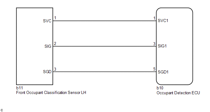
The front occupant classification sensor LH circuit consists of the occupant detection ECU and front occupant classification sensor LH.
DTC B1780 is stored when a malfunction is detected in the front occupant classification sensor LH circuit.
| DTC No. | Detection Item | DTC Detection Condition | Trouble Area |
|---|---|---|---|
| B1780 | Front Occupant Classification Sensor LH Circuit Malfunction |
|
|
- *: The front occupant classification sensor LH is built into the front seat adjuster assembly RH.
WIRING DIAGRAM
CAUTION / NOTICE / HINT
NOTICE:
After turning the engine switch off, waiting time may be required before disconnecting the cable from the negative (-) battery terminal. Therefore, make sure to read the disconnecting the cable from the negative (-) battery terminal notices before proceeding with work.
Click here .gif)
HINT:
- When DTC B1650 is stored as a result of troubleshooting for the airbag system, check the DTCs stored in the occupant detection ECU. When DTC B1780 is output, perform troubleshooting for this DTC first.
- If it is difficult to perform troubleshooting (wire harness inspection), remove the front passenger seat installation bolts to see under the seat cushion.
- In the above case, lift and hold the seat so that it does not fall down. Hold the seat only as necessary because holding the seat for a long period of time may cause seat rail deformation.
PROCEDURE
| 1. | CHECK CONNECTORS |
(a) Turn the engine switch off.
(b) Disconnect the cable from the negative (-) battery terminal.
(c) Check that the connectors are properly connected to the occupant detection ECU and front occupant classification sensor LH.
OK:
The connectors are properly connected.
HINT:
If the connectors are not properly connected, reconnect the connectors and proceed to the next inspection.
(d) Disconnect the connectors from the occupant detection ECU and front occupant classification sensor LH.
(e) Check that the terminals of the connectors are not deformed or damaged.
OK:
The terminals are not deformed or damaged.
| NG | .gif) | REPLACE FRONT SEAT WIRE RH |
|
.gif)
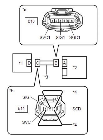
| 2. | CHECK FRONT SEAT WIRE RH (SHORT TO B+) |
| (a) Connect the cable to the negative (-) battery terminal. |
|
(b) Turn the engine switch on (IG).
(c) Measure the voltage according to the value(s) in the table below.
Standard Voltage:
| Tester Connection | Condition | Specified Condition |
|---|---|---|
| b10-1 (SVC1) - Body ground | Engine switch on (IG) | Below 1 V |
| b10-3 (SIG1) - Body ground | Engine switch on (IG) | Below 1 V |
| b10-5 (SGD1) - Body ground | Engine switch on (IG) | Below 1 V |
(d) Turn the engine switch off.
(e) Disconnect the cable from the negative (-) battery terminal.
| NG | | GO TO STEP 12 |
|
| 3. | CHECK FRONT SEAT WIRE RH (OPEN) |
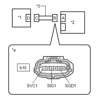
| (a) Using service wires, connect terminals 1 (SVC) and 3 (SGD), and terminals 2 (SIG) and 3 (SGD) of connector C. NOTICE: Do not forcibly insert the service wire into the terminals of the connector when connecting the wire. |
|
(b) Measure the resistance according to the value(s) in the table below.
Standard Resistance:
| Tester Connection | Condition | Specified Condition |
|---|---|---|
| b10-1 (SVC1) - b10-5 (SGD1) | Always | Below 1 Ω |
| b10-3 (SIG1) - b10-5 (SGD1) | Always | Below 1 Ω |
(c) Disconnect the service wires from connector C.
| NG | | REPLACE FRONT SEAT WIRE RH |
|
| 4. | CHECK FRONT SEAT WIRE RH (SHORT) |
| (a) Measure the resistance according to the value(s) in the table below. Standard Resistance:
|
|
| NG | | REPLACE FRONT SEAT WIRE RH |
|
| 5. | CHECK FRONT SEAT WIRE RH (SHORT TO GROUND) |
| (a) Measure the resistance according to value(s) in the table below. Standard Resistance:
|
|
| NG | | REPLACE FRONT SEAT WIRE RH |
|
| 6. | CHECK DTC |
(a) Connect the connectors to the occupant detection ECU and front occupant classification sensor LH.
(b) Connect the cable to the negative (-) battery terminal.
(c) Clear the DTCs stored in the occupant detection ECU.
Click here
(d) Clear the DTCs stored in the airbag sensor assembly.
Click here
(e) Turn the engine switch off.
(f) Turn the engine switch on (IG), and wait for at least 10 seconds.
(g) Check for DTCs.
Click here
OK:
DTC B1780 is not output.
HINT:
Codes other than DTC B1780 may be output at this time, but they are not related to this check.
(h) Turn the engine switch off.
| OK | | USE SIMULATION METHOD TO CHECK |
|
| 7. | CHECK OCCUPANT DETECTION ECU |
(a) Disconnect the cable from the negative (-) battery terminal.
(b) Replace the occupant detection ECU with a known good one.
Click here
HINT:
Perform the following inspection using known good parts from another vehicle if possible.
(c) Connect the cable to the negative (-) battery terminal.
(d) Clear the DTCs stored in the occupant detection ECU.
Click here
(e) Clear the DTCs stored in the airbag sensor assembly.
Click here
(f) Turn the engine switch off.
(g) Turn the engine switch on (IG), and wait for at least 10 seconds.
(h) Check for DTCs.
Click here
OK:
DTC B1780 is not output.
HINT:
Codes other than DTC B1780 may be output at this time, but they are not related to this check.
(i) Turn the engine switch off.
(j) Disconnect the cable from the negative (-) battery terminal.
(k) Restore the occupant detection ECU that was installed for testing to its original location.
Click here
| NG | | GO TO STEP 10 |
|
| 8. | REPLACE OCCUPANT DETECTION ECU |
(a) Turn the engine switch off.
(b) Disconnect the cable from the negative (-) battery terminal.
(c) Replace the occupant detection ECU with a new one.
Click here
(d) Connect the cable to the negative (-) battery terminal.
|
| 9. | PERFORM ZERO POINT CALIBRATION |
(a) Using the Techstream, perform Zero Point Calibration.
Click here
| Tester Display |
|---|
| Zero Point Calibration |
| NEXT | | END |
| 10. | REPLACE FRONT SEAT ADJUSTER ASSEMBLY RH |
(a) Turn the engine switch off.
(b) Disconnect the cable from the negative (-) battery terminal.
(c) Replace the front seat adjuster assembly RH.
Click here
(d) Connect the cable to the negative (-) battery terminal.
|
| 11. | PERFORM ZERO POINT CALIBRATION |
(a) Using the Techstream, perform Zero Point Calibration.
Click here
| Tester Display |
|---|
| Zero Point Calibration |
| NEXT | | END |
| 12. | REPLACE FRONT SEAT ADJUSTER ASSEMBLY RH |
(a) Replace the front seat adjuster assembly RH.
Click here
NOTICE:
Replace the front seat wire RH at the same time.
HINT:
When the front seat wire RH has a short to B+, the front occupant classification sensor LH will be damaged. Therefore, replace the front seat wire RH and the front seat adjuster assembly RH, which includes the front occupant classification sensor LH.
(b) Connect the cable to the negative (-) battery terminal.
|
| 13. | PERFORM ZERO POINT CALIBRATION |
(a) Using the Techstream, perform Zero Point Calibration.
Click here
| Tester Display |
|---|
| Zero Point Calibration |
| NEXT | | END |
 Passenger Side Buckle Switch Circuit Malfunction (B1771)
DESCRIPTION The passenger side buckle switch circuit consists of the occupant detection ECU and passenger side buckle switch (front seat inner belt assembly RH). DTC B1771 is stored when a malfunction ...
 Front Occupant Classification Sensor LH Collision Detection (B1785)
DESCRIPTION DTC B1785 is stored when the occupant detection ECU receives a collision detection signal sent by the front occupant classification sensor LH in the case of an accident. DTC B1785 is also ...
Other materials:
Lexus RX (RX 350L, RX450h) 2016-2026 Repair Manual > Radiator: On-vehicle Inspection
ON-VEHICLE INSPECTION CAUTION / NOTICE / HINT CAUTION: Do not remove the radiator cap sub-assembly while the engine and radiator assembly are still hot. Pressurized, hot engine coolant and steam may be released and cause serious burns. PROCEDURE 1. CHECK RADIATOR CAP SUB-ASSEMBLY CAUTION: Do not re ...
Lexus RX (RX 350L, RX450h) 2016-2026 Repair Manual > Wireless Door Lock Control System: No Answer-Back
DESCRIPTION In some cases, wireless door lock control functions are normal but the hazard warning light and/or wireless door lock buzzer answer-back function does not operate. In such cases, hazard warning light and wireless door lock buzzer signal outputs from the main body ECU (multiplex network b ...
Lexus RX (RX 350L, RX450h) 2016-{YEAR} Owners Manual
- For your information
- Pictorial index
- For safety and security
- Instrument cluster
- Operation of each component
- Driving
- Lexus Display Audio system
- Interior features
- Maintenance and care
- When trouble arises
- Vehicle specifications
- For owners
Lexus RX (RX 350L, RX450h) 2016-{YEAR} Repair Manual

0.0103