Lexus RX (RX 350L, RX450h) 2016-2026 Repair Manual: Removal
REMOVAL
CAUTION / NOTICE / HINT
The necessary procedures (adjustment, calibration, initialization, or registration) that must be performed after parts are removed, installed, or replaced during the horn button assembly removal/installation are shown below.
Necessary Procedure After Parts Removed/Installed/Replaced| Replacement Part or Procedure | Necessary Procedures | Effects / Inoperative when not performed | Link |
|---|---|---|---|
| Disconnect cable from negative battery terminal | Memorize steering angle neutral point | Lane control system | |
| Pre-collision system | |||
| Intelligent clearance sonar system*1 | |||
| Lighting system (w/ Automatic Headlight Beam Level Control System) | | ||
| Parking assist monitor system | | ||
| Panoramic view monitor system | | ||
| Initialize back door lock | Power door lock control system | | |
| Reset back door close position | Power back door system | |
*1: When performing learning using the Techstream.
Click here .gif)
PROCEDURE
1. PRECAUTION
CAUTION:
Be sure to read Precaution thoroughly before servicing.
Click here
.png)
NOTICE:
After turning the engine switch off, waiting time may be required before disconnecting the cable from the negative (-) battery terminal. Therefore, make sure to read the disconnecting the cable from the negative (-) battery terminal notices before proceeding with work.
Click here
2. DISCONNECT CABLE FROM NEGATIVE BATTERY TERMINAL
CAUTION:
Wait at least 90 seconds after disconnecting the cable from the negative (-) battery terminal to disable the SRS system.
.png)
NOTICE:
When disconnecting the cable, some systems need to be initialized after the cable is reconnected.
Click here
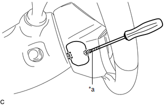
3. REMOVE LOWER NO. 3 STEERING WHEEL COVER
| (a) Using a screwdriver with its tip wrapped with protective tape, disengage the claw and guide to remove the lower No. 3 steering wheel cover. |
|
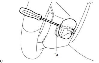
4. REMOVE LOWER NO. 2 STEERING WHEEL COVER
| (a) Using a screwdriver with its tip wrapped with protective tape, disengage the claw and guide to remove the lower No. 2 steering wheel cover. |
|
5. REMOVE HORN BUTTON ASSEMBLY
CAUTION:
When storing the horn button assembly, keep the airbag deployment side facing upward.
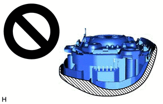
.png) | Deployment Side |
(a) Check that the engine switch is off.
(b) Check that the cable is disconnected from the negative (-) battery terminal.
CAUTION:
Wait at least 90 seconds after disconnecting the cable from the negative (-) battery terminal to disable the SRS system.
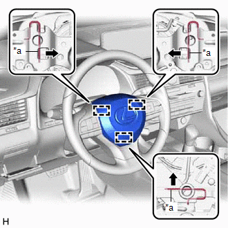
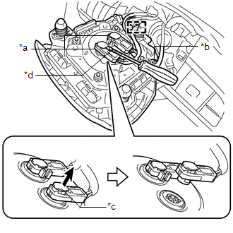
| (c) Using a screwdriver, push in the 3 torsion springs to disengage the 3 pins as shown in the illustration. NOTICE: Do not drop the horn button assembly. HINT: Insert the screwdriver from the installation holes for the lower No. 3 steering wheel cover and lower No. 2 steering wheel cover. |
|
(d) Pull out the horn button assembly from the steering wheel assembly and hold the horn button assembly with one hand.
NOTICE:
When separating the horn button assembly, do not pull the airbag wire harness.
| (e) Disconnect the horn connector from the horn button assembly. |
|
(f) Using a screwdriver with its tip wrapped with protective tape, release the 2 airbag connector locks.
(g) Disconnect the 2 airbag connectors.
(h) Disengage the wire harness clamp to remove the horn button assembly
NOTICE:
When disconnecting any airbag connector, take care not to damage the airbag wire harness.
 On-vehicle Inspection
ON-VEHICLE INSPECTION CAUTION / NOTICE / HINT CAUTION: Be sure to correctly follow the removal and installation procedures for the horn button assembly. PROCEDURE 1. INSPECT HORN BUTTON ASSEMBLY (for ...
 Installation
INSTALLATION PROCEDURE 1. INSTALL HORN BUTTON ASSEMBLY (a) Check that the engine switch is off. (b) Check that the cable is disconnected from the negative (-) battery terminal. CAUTION: Wait at least ...
Other materials:
Lexus RX (RX 350L, RX450h) 2016-2026 Repair Manual > Shift Lever: Inspection
INSPECTION PROCEDURE 1. INSPECT SHIFT LOCK CONTROL ECU HINT: If the results of the following inspections are as specified but a malfunction has occurred, replace the transmission floor shift assembly. (a) Inspect wire harness: (1) Disconnect the shift lock control ECU connector. (2 ...
Lexus RX (RX 350L, RX450h) 2016-2026 Repair Manual > Can Communication System: Steering Angle Sensor Communication Stop Mode
DESCRIPTION Detection Item Symptom Trouble Area Steering Angle Sensor Communication Stop Mode Either condition is met:
"Spiral cable (Steering Angle Sensor)" is not displayed on the CAN Bus Check screen of the Techstream.
Click here
Communication system DTCs (DTCs that start w ...
Lexus RX (RX 350L, RX450h) 2016-{YEAR} Owners Manual
- For your information
- Pictorial index
- For safety and security
- Instrument cluster
- Operation of each component
- Driving
- Lexus Display Audio system
- Interior features
- Maintenance and care
- When trouble arises
- Vehicle specifications
- For owners
Lexus RX (RX 350L, RX450h) 2016-{YEAR} Repair Manual

0.0095