Lexus RX (RX 350L, RX450h) 2016-2026 Repair Manual: Removal
REMOVAL
CAUTION / NOTICE / HINT
The necessary procedures (adjustment, calibration, initialization, or registration) that must be performed after parts are removed and installed, or replaced during antenna cord sub-assembly removal/installation are shown below.
Necessary Procedures After Parts Removed/Installed/Replaced| Replaced Part or Performed Procedure | Necessary Procedure | Effect/Inoperative Function when Necessary Procedure not Performed | Link |
|---|---|---|---|
| Disconnect cable from negative battery terminal | Memorize steering angle neutral point | Lane Control System | |
| Pre-collision System | |||
| Intelligent Clearance Sonar System*1 | |||
| Parking Assist Monitor System | | ||
| Panoramic View Monitor System | | ||
| Lighting System (w/ Automatic Headlight Beam Level Control System) | | ||
| Initialize back door lock | Power Door Lock Control System | | |
| Reset back door close position | Power Back Door System (w/ Outside Door Control Switch) | | |
| Removal/installation of the spiral cable with sensor sub-assembly |
| Parking assist monitor system | |
| Steering angle neutral point (Initialize panoramic view monitor system) | Panoramic view monitor system | | |
| Steering angle neutral point (Initialize intelligent clearance sonar system) | Intelligent clearance sonar system | |
*1: When performing learning using the Techstream.
Click here .gif)
CAUTION:
Some of these service operations affect the SRS airbag system. Read the precautionary notices concerning the SRS airbag system before servicing.
Click here
.png)
PROCEDURE
1. REMOVE INSTRUMENT PANEL SAFETY PAD SUB-ASSEMBLY
Click here
2. REMOVE NO. 4 HEATER TO REGISTER DUCT
Click here
3. REMOVE NO. 2 SIDE DEFROSTER NOZZLE DUCT
Click here
4. REMOVE ANTENNA CORD SUB-ASSEMBLY
| (a) Disengage the 2 claws. |
|
.png)
(b) Disconnect the connector.
(c) Disengage each clamp and remove the antenna cord sub-assembly.
.png)
| *a | w/ Manual (SOS) Switch | - | - |
5. REMOVE ROOF HEADLINING ASSEMBLY
Click here
6. REMOVE NO. 2 ANTENNA CORD SUB-ASSEMBLY
(a) Remove the adhesive tape from the roof headlining assembly.
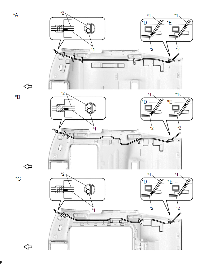
| *A | for Standard Roof | *B | for Sliding Roof |
| *C | for Panoramic Moon Roof | *D | for TMC Made |
| *E | for TMMC Made | - | - |
| *1 | No. 2 Antenna Cord Sub-assembly | *2 | Washer Hose Assembly |
.png) | Adhesive Tape | .png) | Front |
(b) Remove the No. 2 antenna cord sub-assembly from the roof headlining assembly.
7. REMOVE BACK WINDOW UPPER PANEL TRIM
Click here
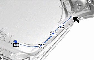
8. REMOVE NO. 3 ANTENNA CORD SUB-ASSEMBLY
| (a) Disengage each clamp. |
|
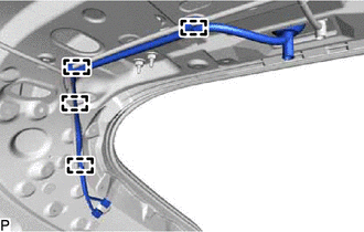
| (b) Disconnect each connector. |
|
| (c) Disengage the 2 grommets and remove the No. 3 antenna cord sub-assembly. |
|
9. REMOVE BACK DOOR TRIM COVER LH
Click here
10. REMOVE BACK DOOR TRIM COVER RH
HINT:
Use the same procedure as for the LH side.
11. REMOVE BACK DOOR LOCK COVER
Click here
12. REMOVE BACK DOOR TRIM BASE
Click here
13. REMOVE DOOR PULL HANDLE
Click here
14. REMOVE NO. 1 LUGGAGE COMPARTMENT LIGHT ASSEMBLY
Click here
15. REMOVE BACK DOOR TRIM PANEL ASSEMBLY
Click here
16. REMOVE NO. 4 ANTENNA CORD SUB-ASSEMBLY
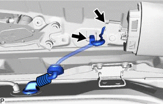
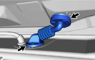
| (a) Disconnect the connector. |
|
(b) Disengage 4 clamps and remove the No. 4 antenna cord sub-assembly.
 Components
COMPONENTS ILLUSTRATION *A w/o Manual (SOS) Switch *B w/ Manual (SOS) Switch *1 ANTENNA CORD SUB-ASSEMBLY *2 NO. 2 SIDE DEFROSTER NOZZLE DUCT *3 NO. 4 HEATER TO REGISTER DUCT ...
 Installation
INSTALLATION PROCEDURE 1. INSTALL NO. 4 ANTENNA CORD SUB-ASSEMBLY (a) Engage the 4 clamps to install the No. 4 antenna cord sub-assembly. (b) Connect the connector. 2. INSTALL BACK DOOR TRIM PANEL ASS ...
Other materials:
Lexus RX (RX 350L, RX450h) 2016-2026 Repair Manual > Front Passenger Airbag Assembly: Disposal
DISPOSAL CAUTION / NOTICE / HINT CAUTION: Before performing pre-disposal deployment of any SRS part, review and closely follow all applicable environmental and hazardous material regulations. Pre-disposal deployment may be considered hazardous material treatment. PROCEDURE 1. PRECAUTION CAUTION:
...
Lexus RX (RX 350L, RX450h) 2016-2026 Repair Manual > Audio And Visual System (for 8 Inch Display): Remote Touch Screen Does not Generate Vibration Feedback
DESCRIPTION When each button displayed on the multi-display assembly is selected via remote touch screen operation, the remote touch screen generates vibration feedback according to communication between the remote touch and radio receiver assembly. CAUTION / NOTICE / HINT NOTICE: Depending on the p ...
Lexus RX (RX 350L, RX450h) 2016-{YEAR} Owners Manual
- For your information
- Pictorial index
- For safety and security
- Instrument cluster
- Operation of each component
- Driving
- Lexus Display Audio system
- Interior features
- Maintenance and care
- When trouble arises
- Vehicle specifications
- For owners
Lexus RX (RX 350L, RX450h) 2016-{YEAR} Repair Manual

0.0128