Lexus RX (RX 350L, RX450h) 2016-2026 Repair Manual: Installation
INSTALLATION
PROCEDURE
1. INSTALL NO. 4 ANTENNA CORD SUB-ASSEMBLY
(a) Engage the 4 clamps to install the No. 4 antenna cord sub-assembly.
(b) Connect the connector.
2. INSTALL BACK DOOR TRIM PANEL ASSEMBLY
Click here .gif)
3. INSTALL NO. 1 LUGGAGE COMPARTMENT LIGHT ASSEMBLY
Click here
4. INSTALL DOOR PULL HANDLE
Click here
5. INSTALL BACK DOOR TRIM BASE
Click here
6. INSTALL BACK DOOR LOCK COVER
Click here
7. INSTALL BACK DOOR TRIM COVER LH
Click here
8. INSTALL BACK DOOR TRIM COVER RH
HINT:
Use the same procedure as for the LH side.
9. INSTALL NO. 3 ANTENNA CORD SUB-ASSEMBLY
| (a) Engage the 2 grommets as shown in the illustration. |
|
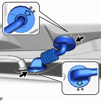
| (b) Connect each connector. NOTICE: Route the No. 3 antenna cord sub-assembly around the right side of the connector as shown in the illustration. |
|
(c) Engage each clamp to install the No. 3 antenna cord sub-assembly.
10. INSTALL BACK WINDOW UPPER PANEL TRIM
Click here
11. INSTALL NO. 2 ANTENNA CORD SUB-ASSEMBLY (for TMC Made)
HINT:
Butyl tape and adhesive tape are not available as supply parts. If these pieces of tape still have enough adhesion to secure the No. 2 antenna cord sub-assembly to the roof headlining assembly, reuse them. If the adhesive tape and/or the butyl tape is no longer sticky, apply new tape following the procedure below.
(a) Apply new butyl tape.
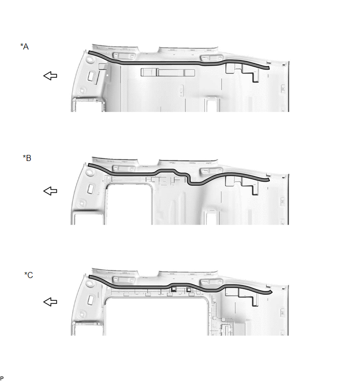
| *A | for Standard Roof | *B | for Sliding Roof |
| *C | for Panoramic Moon Roof | - | - |
.png) | Butyl tape | .png) | Front |
(1) Remove the old butyl tape from the roof headlining assembly.
(2) Prepare an appropriate amount of new butyl tape.
HINT:
Be careful not to touch the adhesive surface.
(3) Apply the butyl tape to the roof headlining assembly while aligning the tape with the markings on the roof headlining assembly.
(4) Peel off the release paper from the butyl tape.
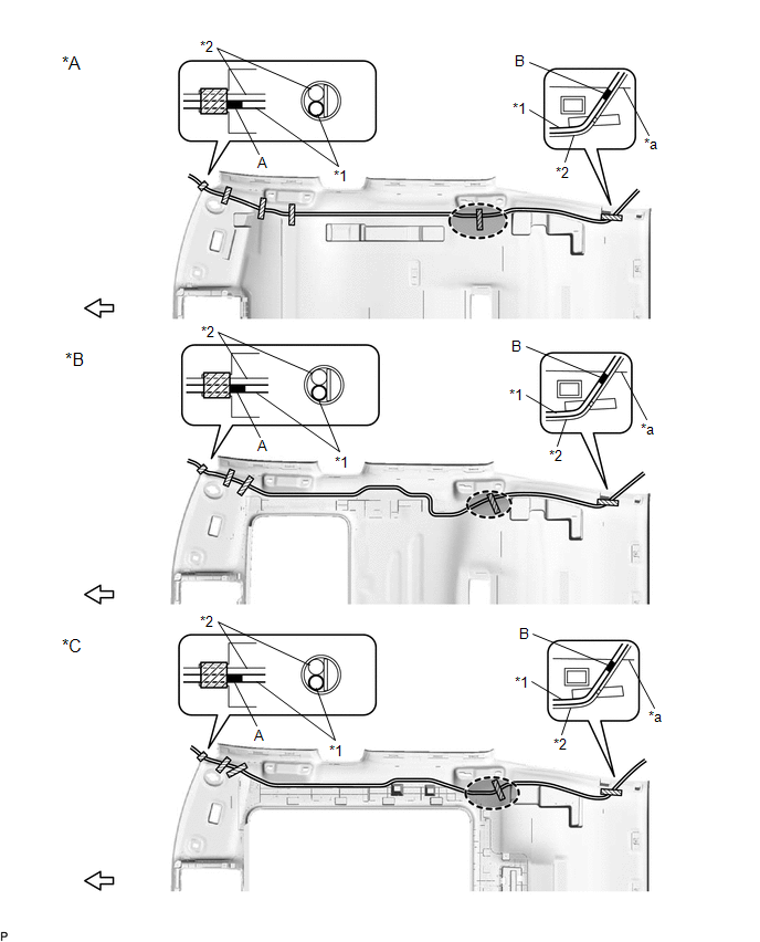
(b) Align the marking tape on the No. 2 antenna cord sub-assembly with the markings on the roof headlining assembly and install the No. 2 antenna cord sub-assembly to the butyl tape.
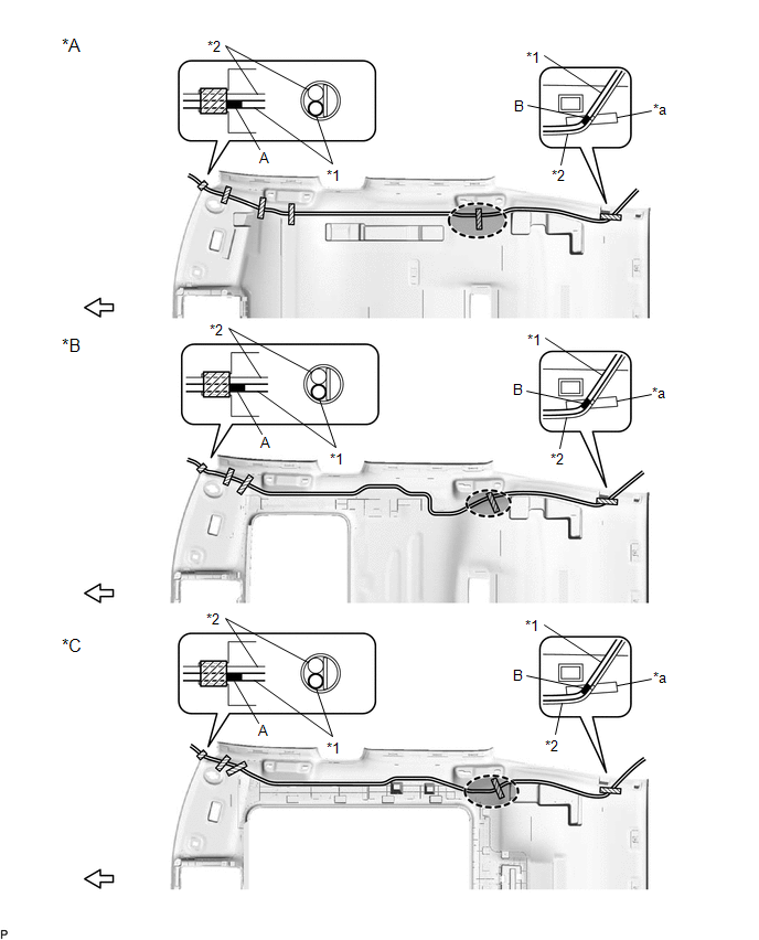
| *A | for Standard Roof | *B | for Sliding Roof |
| *C | for Panoramic Moon Roof | - | - |
| *1 | No. 2 Antenna Cord Sub-assembly | *2 | Washer Hose Assembly |
| *a | Marking | - | - |
.png) | Adhesive Tape | .png) | Marking Tape |
.png) | Adjustment Area | | Front |
(c) Put the pieces of adhesive tape back to the positions shown in the illustration to secure the No. 2 antenna cord sub-assembly and washer hose assembly to the roof headlining assembly.
HINT:
- If the tape is no longer sticky, use other tape, such as packing tape, that has enough adhesion to secure the antenna cord to the roof headlining assembly.
- Align the marking tape (A) on the No. 2 antenna cord sub-assembly with the base of the protrusion on the front right side of the roof headlining assembly and wrap tape around the No. 2 antenna cord sub-assembly, washer hose assembly and roof headlining assembly to secure them.
- Align the marking tape (B) on the No. 2 antenna cord sub-assembly with the marking on the rear of the roof headlining assembly and secure the No. 2 antenna cord sub-assembly and washer hose assembly with the No. 2 antenna cord sub-assembly on the outer side of the washer hose assembly.
- Secure the extra length of the No. 2 antenna cord sub-assembly in the adjustment area shown in the illustration.
12. INSTALL NO. 2 ANTENNA CORD SUB-ASSEMBLY (for TMMC Made)
(a) When Reusing the Roof Headlining Assembly:
HINT:
Butyl tape and adhesive tape are not available as supply parts. If these pieces of tape still have enough adhesion to secure the No. 2 antenna cord sub-assembly to the roof headlining assembly, reuse them. If the adhesive tape and/or the butyl tape is no longer sticky, apply new tape following the procedure below.
(1) Apply new butyl tape.
| *A | for Standard Roof | *B | for Sliding Roof |
| *C | for Panoramic Moon Roof | - | - |
| | Butyl tape | | Front |
- Remove the old butyl tape from the roof headlining assembly.
-
Prepare an appropriate amount of new butyl tape.
HINT:
Be careful not to touch the adhesive surface.
- Apply the butyl tape to the roof headlining assembly while aligning the tape with the markings on the roof headlining assembly.
- Peel off the release paper from the butyl tape.
(b) When Replacing the Roof Headlining Assembly:
(1) Apply new butyl tape.

| *A | for Standard Roof | *B | for Sliding Roof |
| *C | for Panoramic Moon Roof | - | - |
| | Butyl tape | | Double-sided Tape |
| | Front | - | - |
-
Prepare an appropriate amount of new butyl tape.
HINT:
Be careful not to touch the adhesive surface.
- Apply the butyl tape to the roof headlining assembly while aligning the tape with the markings on the roof headlining assembly.
- Peel off the release paper from the butyl tape.
-
Remove the release paper from the double-sided tape.
HINT:
After removing the release paper, keep the exposed adhesive free from foreign matter.
(c) Align the marking tape on the No. 2 antenna cord sub-assembly with the markings on the roof headlining assembly and install the No. 2 antenna cord sub-assembly to the butyl tape.
| *A | for Standard Roof | *B | for Sliding Roof |
| *C | for Panoramic Moon Roof | - | - |
| *1 | NO. 2 ANTENNA CORD SUB-ASSEMBLY | *2 | WASHER HOSE ASSEMBLY |
| *a | Rear Right Side Edge Of The Roof Headlining Assembly | - | - |
| | Adhesive Tape | | Marking Tape |
| | Adjustment Area | | Front |
(d) Put the pieces of adhesive tape back to the positions shown in the illustration to secure the No. 2 antenna cord sub-assembly and washer hose assembly to the roof headlining assembly.
HINT:
- If the tape is no longer sticky, use other tape, such as packing tape, that has enough adhesion to secure the antenna cord to the roof headlining assembly.
- Align the marking tape (A) on the No. 2 antenna cord sub-assembly with the base of the protrusion on the front right side of the roof headlining assembly and wrap tape around the No. 2 antenna cord sub-assembly, washer hose assembly and roof headlining assembly to secure them.
- Align the marking tape (B) on the No. 2 antenna cord sub-assembly with the rear right side edge of the rear of the roof headlining assembly and secure the No. 2 antenna cord sub-assembly and washer hose assembly with the No. 2 antenna cord sub-assembly on the outer side of the washer hose assembly.
- Secure the extra length of the No. 2 antenna cord sub-assembly in the adjustment area shown in the illustration.
13. INSTALL ROOF HEADLINING ASSEMBLY
Click here
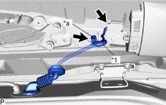
14. INSTALL ANTENNA CORD SUB-ASSEMBLY
(a) Engage each clamp to install the antenna cord sub-assembly.
(b) Connect the connector.
(c) Engage the 2 claws.
15. INSTALL NO. 2 SIDE DEFROSTER NOZZLE DUCT
Click here
16. INSTALL NO. 4 HEATER TO REGISTER DUCT
Click here
17. INSTALL INSTRUMENT PANEL SAFETY PAD SUB-ASSEMBLY
Click here
 Removal
REMOVAL CAUTION / NOTICE / HINT The necessary procedures (adjustment, calibration, initialization, or registration) that must be performed after parts are removed and installed, or replaced during ant ...
 Radio Receiver
...
Other materials:
Lexus RX (RX 350L, RX450h) 2016-2026 Repair Manual > Dynamic Radar Cruise Control System: Software Incompatibility with Body Control Module Not Programmed (U032251)
DESCRIPTION If the forward recognition camera cannot verify the vehicle information sent from the main body ECU (multiplex network body ECU), the forward recognition camera stores DTC U032251. DTC No. Detection Item DTC Detection Condition Trouble Area MIL DTC Output from U032251 ...
Lexus RX (RX 350L, RX450h) 2016-2026 Repair Manual > Steering Heater Switch: Installation
INSTALLATION PROCEDURE 1. INSTALL STEERING HEATER SWITCH (INTEGRATION CONTROL AND PANEL ASSEMBLY) (a) Engage the 4 claws to install the steering heater switch (integration control and panel assembly). 2. INSTALL LOWER INSTRUMENT PANEL FINISH PANEL SUB-ASSEMBLY Click here 3. CONNECT HOOD LOCK CONT ...
Lexus RX (RX 350L, RX450h) 2016-{YEAR} Owners Manual
- For your information
- Pictorial index
- For safety and security
- Instrument cluster
- Operation of each component
- Driving
- Lexus Display Audio system
- Interior features
- Maintenance and care
- When trouble arises
- Vehicle specifications
- For owners
Lexus RX (RX 350L, RX450h) 2016-{YEAR} Repair Manual

0.0101