Lexus RX (RX 350L, RX450h) 2016-2026 Repair Manual: Operation Check
OPERATION CHECK
NOTICE:
Make sure that the smart access system with push-button start (for Start Function) has not been canceled before performing this inspection.
Click here .gif)
OPERATION DESCRIPTION
(a) Power source state when a door is unlocked via a wireless unlock or entry unlock operation:
HINT:
When the door is unlocked using the mechanical key built into the electrical key transmitter sub-assembly, the power source state cannot be changed. By holding the logo side of the electrical key transmitter sub-assembly near the engine switch while depressing the brake pedal, the power source state can be changed.
(1) When the electrical key transmitter sub-assembly is in a vehicle interior detection area and the brake pedal is depressed, the engine is started by pressing the engine switch.
(2) When the electrical key transmitter sub-assembly is in a vehicle interior detection area and the brake pedal is not depressed, the power source mode is changed by pressing the engine switch. The power source mode changes in the following order every time the engine switch is pressed: off → on (ACC) → on (IG) → off.
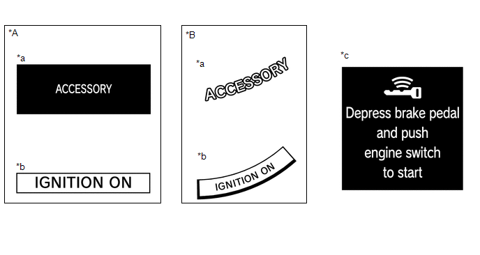
(3) After getting into the vehicle while carrying the electrical key transmitter sub-assembly when the engine switch is off, if the engine switch is pressed while not depressing the brake pedal, the power source mode will change to on (ACC) and "ACCESSORY" will be displayed on the multi-information display.
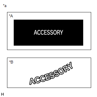
| *A | for Optitron Meter Type |
| *B | for TFT Meter Type |
| *a | "ACCESSORY" Display |
(4) After getting into the vehicle while carrying the electrical key transmitter sub-assembly when the engine switch is off, if the engine switch is pressed 2 times without depressing the brake pedal, the power source mode will change to on (IG) and "IGNITION ON" will be displayed on the multi-information display.
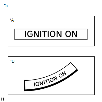
| *A | for Optitron Meter Type |
| *B | for TFT Meter Type |
| *a | "IGNITION ON" Display |
(5) After getting into the vehicle while carrying the electrical key transmitter sub-assembly when the engine switch is off, if the brake pedal is depressed while the shift lever is in P, the key indicator display will be displayed on the multi-information display.
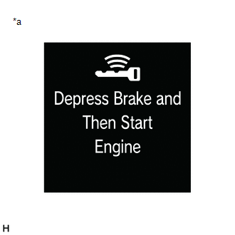
| *a | Key Indicator Display |
(6) The engine will start if the engine switch is pressed when the key indicator display is displayed.
(b) Changing the power source mode when the electrical key transmitter sub-assembly is not operating correctly due to wave interference or transmitter battery depletion:
(1) Unlock the door using the built-in mechanical key and get into the vehicle while carrying the electrical key transmitter sub-assembly.
(2) While depressing the brake pedal and facing the logo side of the electrical key transmitter sub-assembly toward the engine switch, hold the electrical key transmitter sub-assembly near the engine switch.
(3) A buzzer in the combination meter assembly will sound and the power source mode will change to on (IG) and "IGNITION ON" will be displayed on the multi-information display.
| *A | for Optitron Meter Type |
| *B | for TFT Meter Type |
| *a | "IGNITION ON" Display |
(4) Pressing the engine switch without depressing the brake pedal changes the power source mode from on (IG) to off.
(c) Starting the engine when the electrical key transmitter sub-assembly does not operate correctly due to wave interference or transmitter battery depletion:
(1) Unlock the door using the built-in mechanical key and get into the vehicle while carrying the electrical key transmitter sub-assembly.
(2) While depressing the brake pedal with the shift lever in P and facing the logo side of the electrical key transmitter sub-assembly toward the engine switch, hold the electrical key transmitter sub-assembly near the engine switch.
(3) A buzzer in the combination meter assembly will sound, the power source mode will change to on (IG) and the key indicator display will be displayed on the multi-information display.
| *a | Key Indicator Display |
(4) Press the engine switch with the brake pedal depressed to start the engine.
CHECK PUSH-BUTTON START FUNCTION
(a) Check the push-button start function:
(1) Unlock the doors by performing a wireless unlock or entry unlock operation.
(2) Get into the vehicle while carrying the electrical key transmitter sub-assembly with the engine switch off. With the shift lever in P, check that the key indicator display is displayed when the brake pedal is depressed. Check that the engine starts when the engine switch is pressed after the key indicator display is displayed on the multi-information display.
| *a | Key Indicator Display |
(3) While carrying the electrical key transmitter sub-assembly, check that the power source mode changes in the following order when the engine switch is pressed with the brake pedal released: off → on (ACC) → on (IG) → off.
HINT:
If the engine switch is pressed with the engine switch on (IG) and the shift lever not in P, the power source mode will not change to off, but to on (ACC).
(4) With the shift lever in P, check that the steering lock operates when a door is opened.
HINT:
When the engine switch is pressed after the vehicle is stopped, the engine will stop and all power will turn off. However, if the shift lever is not in P when the engine switch is pressed with the vehicle stopped, the power source mode will not change to off, but to on (ACC).
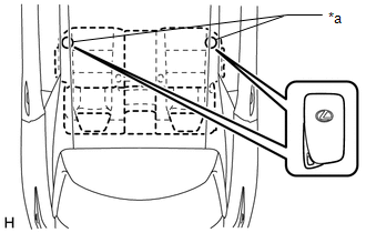
(5) Check the push-button start function operation range for the front side. Place the electrical key transmitter sub-assembly at either inspection point so that it is facing the direction shown in the illustration, and then check that the engine can be started.
NOTICE:
Even if the electrical key transmitter sub-assembly is in a vehicle interior detection area, it may not be properly detected if it is on the instrument panel, in the glove box or on the floor.
HINT:
-
Communication may not be possible if the electrical key transmitter sub-assembly is within 0.2 m (0.656 ft.) of the No. 1 indoor electrical key antenna assembly (front floor).
Click here
- Perform this inspection for both inspection points.
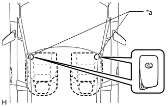
| *a | Inspection Point |
(6) Check the push-button start function operation range for the rear side. Place the electrical key transmitter sub-assembly at either inspection point so that it is facing the direction shown in the illustration, and then check that the engine can be started.
NOTICE:
Even if the electrical key transmitter sub-assembly is in a vehicle interior detection area, it may not be properly detected if it is on the instrument panel, in the glove box or on the floor.
HINT:
-
Communication may not be possible if the electrical key transmitter sub-assembly is within 0.2 m (0.656 ft.) of the center of the No. 2 indoor electrical key antenna assembly (rear floor).
Click here
- Perform this inspection for both inspection points.
| *a | Inspection Point |
(7) Check the push-button start function operation range for the luggage compartment. Place the electrical key transmitter sub-assembly at either inspection point so that it is facing the direction shown in the illustration, and then check that the engine can be started.
NOTICE:
Even if the electrical key transmitter sub-assembly is in a vehicle interior detection area, it may not be properly detected if it is on the instrument panel, in the glove box or on the floor.
HINT:
-
Communication may not be possible if the electrical key transmitter sub-assembly is within 0.2 m (0.656 ft.) of the center of the No. 3 indoor electrical key antenna assembly (inside luggage compartment).
Click here
- Perform this inspection for both inspection points.
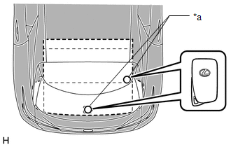
| *a | Inspection Point |
CHECK TRANSMITTER BATTERY SAVING MODE FUNCTION
(a) Check the transmitter battery saving mode function:
(1) Press the unlock switch of the electrical key transmitter sub-assembly twice while pressing the lock switch and check that the electrical key transmitter sub-assembly LED blinks 4 times and enters transmitter battery saving mode.
(2) Check that the smart access system with push-button start (for Start Function) does not operate while in transmitter battery saving mode.
HINT:
To cancel transmitter battery saving mode, press a switch of the electrical key transmitter sub-assembly.
CHECK POWER SOURCE MODE CHANGING FUNCTION
(a) Check the engine switch.
(1) Check that the power source mode changes according to the chart below.
| Shift Position | Brake Pedal | Power Source Mode when Engine Switch Pressed |
|---|---|---|
| P | Released | Off → on (ACC) → on (IG) → off |
| P | Released | Engine running → off |
| P | Released | On (ACC)* → off |
| P | Depressed | Off → engine starts |
| P | Depressed | On (ACC) → engine starts |
| P | Depressed | On (IG) → engine starts |
| P | Depressed | Engine running → off |
| P | Depressed | On (ACC)* → off |
| N | Released | Off → on (ACC) → on (IG) (after power source mode changes to on (IG), power source mode changes between on (IG) and on (ACC) every time engine switch is pressed) |
| N | Released | Engine running → on (ACC) |
| N | Depressed | Off → engine starts |
| N | Depressed | On (ACC) → engine starts |
| N | Depressed | On (IG) → engine starts |
| N | Depressed | Engine running → on (ACC) |
| Not P or N | Released | Off → on (ACC) → on (IG) (after power source mode changes to on (IG), power source mode changes between on (IG) and on (ACC) every time engine switch is pressed) |
| Not P or N | Released | Engine running → on (ACC) |
| Not P or N | Depressed | Off → on (IG) |
| Not P or N | Depressed | On (ACC) → on (IG) |
| Not P or N | Depressed | Engine running → on (ACC) |
HINT:
*: This situation is only applicable when the power source mode has changed from on (IG) to on (ACC). (Excluding an emergency stop by pressing the engine switch 3 times quickly or pressing and holding the engine switch for 2 seconds or more.)
CHECK POWER SOURCE MODE INDICATION
(a) Check the key indicator display.
| *A | for Optitron Meter Type | *B | for TFT Meter Type |
| *a | "ACCESSORY" Display | *b | "IGNITION ON" Display |
| *c | Key Indicator Display | - | - |
| Power Source Mode | Multi-information Display |
|---|---|
| Off (Excluding conditions in which the engine can be started) | Off |
| On (ACC) (Excluding conditions in which the engine can be started) | "ACCESSORY" displayed |
| On (IG) (Excluding conditions in which the engine can be started) | "IGNITION ON" displayed |
| Condition in which engine can be started*1 | Key Indicator displayed |
| Engine started | Off |
HINT:
*1: Indicates the conditions in which the engine can be started by pressing the engine switch while either of the following conditions is met:
-
Condition 1
All of the following conditions are met:
- The power source mode was changed from on (IG) to on (ACC).
- Key verification is OK*2 or immobiliser is unset (engine switch is on (ACC) or on (IG)).
- The shift lever is in N and the steering is unlocked.
- The stop light switch assembly is on.
-
Condition 2
All of the following conditions are met:
- The power source mode was not changed from on (IG) to on (ACC).
- Key verification is OK*2 or immobiliser is unset (engine switch is on (ACC) or on (IG)).
- The stop light switch assembly is on.
- The shift lever is in P, or the shift lever is in N with the steering unlocked.
*2: When the electrical key transmitter sub-assembly is in the cabin, the ID code sent as a result of communication between the electrical key transmitter sub-assembly and certification ECU (smart key ECU assembly) and the ID code calculated by the certification ECU (smart key ECU assembly) are compared. If the ID codes match each other, the vehicle recognizes that the electrical key transmitter sub-assembly is in the cabin.
 System Description
SYSTEM DESCRIPTION SYSTEM FUNCTION Function Outline Push-button start function When the electrical key transmitter sub-assembly is brought into the vehicle and verified, this function chang ...
 Customize Parameters
CUSTOMIZE PARAMETERS CUSTOMIZE SMART ACCESS SYSTEM WITH PUSH-BUTTON START (for Start Function) NOTICE:
When the customer requests a change in a function, first make sure that the function can be cu ...
Other materials:
Lexus RX (RX 350L, RX450h) 2016-2026 Repair Manual > Shift Lever: Installation
INSTALLATION PROCEDURE 1. INSTALL TRANSMISSION FLOOR SHIFT ASSEMBLY NOTICE: Check that the park/neutral position switch assembly and the shift lever are in neutral. (a) Temporarily install the transmission floor shift assembly to the vehicle body with the 4 bolts. (b) Tighten the 4 bo ...
Lexus RX (RX 350L, RX450h) 2016-2026 Repair Manual > Air Conditioning System: Rear Blower Motor Circuit
DESCRIPTION The rear blower motor with fan sub-assembly is operated by signals from the air conditioning amplifier assembly. Rear blower motor speed signals are transmitted in accordance with changes in the duty ratio. WIRING DIAGRAM CAUTION / NOTICE / HINT NOTICE: Inspect the fuses for circuits re ...
Lexus RX (RX 350L, RX450h) 2016-{YEAR} Owners Manual
- For your information
- Pictorial index
- For safety and security
- Instrument cluster
- Operation of each component
- Driving
- Lexus Display Audio system
- Interior features
- Maintenance and care
- When trouble arises
- Vehicle specifications
- For owners
Lexus RX (RX 350L, RX450h) 2016-{YEAR} Repair Manual

0.0108