Lexus RX (RX 350L, RX450h) 2016-2026 Repair Manual: Terminals Of Ecu
TERMINALS OF ECU
CHECK CERTIFICATION ECU (SMART KEY ECU ASSEMBLY)
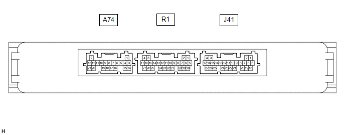
(a) Disconnect the A74, R1 and J41 certification ECU (smart key ECU assembly) connectors.
(b) Measure the voltage and resistance according to the value(s) in the table below.
HINT:
Measure the values on the wire harness side with the connector disconnected.
| Tester Connection | Input/Output | Wiring Color | Terminal Description | Condition | Specified Condition | Related Data List Item |
|---|---|---|---|---|---|---|
| A74-20 (STA) - Body ground | Input | B - Body ground | When starting the engine, this monitors the voltage sent from terminal STAR to the starter relay to judge whether the engine is "being started". | 20°C (68°F) | 106.78 to 115.98 Ω | - |
| A74-9 (STAR) - Body ground | Input/Output | B - Body ground | Outputs voltage to the starter relay
HINT: When Hi is selected, a start request signal (STAR) will not be output even though a start request signal (STSW) is input. | Shift lever in any position other than P or N → Shift lever in P or N (at 20°C (68°F)) | 10 kΩ or higher → 107.05 to 116.33 Ω | - |
| Receives neutral start switch (P, N position detection) signal
| Perform the following operations except while the engine is cranking:
| 30 kΩ or higher → 107.05 to 116.33 Ω | Neutral SW/ Clutch SW | |||
| A74-16 (NE) - Body ground | Input | B - Body ground | Engine speed signal | Always | 10 kΩ or higher | Engine Condition |
| R1-25 (STP1) - Body ground | Input | B - Body ground | Stop light switch signal | Brake pedal depressed → Brake pedal released | 9 V or higher → 1 V or less | Stop Light Switch1 |
| J41-4 (+B) - J41-18 (E) | Input | V - W-B | Power source | Always | 11 to 14 V | - |
| J41-22 (P) - J41-18 (E) | Input | SB - W-B | P position signal | Shift lever in P → Shift lever not in P | 30 kΩ or higher → Below 200 Ω | Shift P Signal |
| J41-18 (E) - Body ground | - | W-B - Body ground | GND | Always | Below 1 Ω | - |
| J41-21 (SSW2) - Body ground | Input | V - Body ground | SSW2 contact signal HINT: Backup for SSW1. Behaves the same way as SSW1. | Engine switch pushed → Engine switch not pushed | Below 15 Ω → 10 kΩ or higher | Start Switch2 |
| J41-23 (SSW1) - Body ground | Input | P - Body ground | SSW1 contact signal | Engine switch pushed → Engine switch not pushed | Below 15 Ω → 10 kΩ or higher | Start Switch1 |
| J41-16 (ACCD) - Body ground | Output | Y - Body ground | ACC signal | 20°C (68°F) | 285.71 to 428.57 Ω | ACC Relay Monitor |
| J41-17 (IG1D) - Body ground | Output | G - Body ground | IG signal | 20°C (68°F) | 55.04 to 88.24 Ω | IG Relay Monitor (Outside) |
| J41-19 (SPD) - Body ground | Input | SB - Body ground | Vehicle speed signal | Always | 30 kΩ or higher | Vehicle Speed Signal |
(c) Reconnect the A74, R1 and J41 certification ECU (smart key ECU assembly) connectors.
(d) Measure the voltage and check for pulses according to the value(s) in the table below.
| Tester Connection | Input/Output | Wiring Color | Terminal Description | Condition | Specified Condition | Related Data List Item |
|---|---|---|---|---|---|---|
| A74-20 (STA) - J41-18 (E) | Input | B - W-B | When starting the engine, this monitors the voltage sent from terminal STAR to the starter relay to judge whether the engine is "being started". | Engine switch pressed and held with brake pedal depressed (starter on) → Approximately 1 second after engine switch released (starter off) | 6 V or higher* → 1.0 V or less | - |
| A74-9 (STAR) - J41-18 (E) | Input/Output | B - W-B | Outputs voltage to the starter relay
HINT: When Hi is selected, a start request signal (STAR) will not be output even though a start request signal (STSW) is input. | Engine switch pressed and held with brake pedal depressed (starter on) → Approximately 1 second after engine switch released (starter off) | 6 V or higher* → 1.0 V or less | - |
| Receives neutral start switch (P, N position detection) signal
| Perform the following operations except while the engine is cranking:
| 9 V or higher → 2.7 V or less | Neutral SW/ Clutch SW | |||
| A74-16 (NE) - J41-18 (E) | Input | B - W-B | Engine speed signal | Idling (engine warmed up) | Pulse generation (See waveform 1) | Engine Condition |
| R1-25 (STP1) - J41-18 (E) | Input | B - W-B | Stop light switch signal | Brake pedal released → Brake pedal depressed | 1 V or less → 9 V or higher | Stop Light Switch1 |
| J41-14 (SLP) - J41-18 (E) | Input | P - W-B | Steering lock position signal | Steering locked → Steering unlocked | 11 to 14 V → 1.5 V or less | Steering Unlock Switch |
| J41-25 (SLR+) - J41-18 (E) | Output | SB - W-B | Steering lock motor operation command signal (Steering lock motor operation permission signal sent from the certification ECU (smart key ECU assembly)) | When a door is opened, the steering lock motor will be operated if all of the following conditions are met:
| Pulse generation (See waveform 2) | - |
| J41-22 (P) - J41-18 (E) | Input | SB - W-B | P position signal | Shift lever in P → Shift lever not in P | 9 V or higher → 2.76 V or less | Shift P Signal |
| J41-21 (SSW2) - J41-18 (E) | Input | V - W-B | SSW2 contact signal HINT: Backup for SSW1. Behaves the same way as SSW1. | Engine switch not pushed → Engine switch pushed | 9 V or higher → 1 V or less | Start Switch2 |
| J41-23 (SSW1) - J41-18 (E) | Input | P - W-B | SSW1 contact signal | Engine switch not pushed → Engine switch pushed | 9 V or higher → 1 V or less | Start Switch1 |
| J41-16 (ACCD) - J41-18 (E) | Output | Y - W-B | ACC signal | Engine switch off → Engine switch on (ACC) | 1 V or less → 8.5 V or higher | ACC Relay Monitor |
| J41-17 (IG1D) - J41-18 (E) | Output | G - W-B | IG signal | Engine switch on (ACC) → Engine switch on (IG) | 1 V or less → 9 V or higher | IG Relay Monitor (Outside) |
| J41-19 (SPD) - J41-18 (E) | Input | SB - W-B | Vehicle speed signal | Vehicle being driven at approx. 5 km/h (3 mph) | Pulse generation (See waveform 3) | Vehicle Speed Signal |
| J41-8 (CLG5) - J41-18 (E) | Output | B - W-B | Output to No. 1 indoor electrical key antenna assembly (front floor) | Procedure:
| Pulse generation (See waveform 4) | Overhead + Front Room (key diagnostic mode) |
| J41-9 (CG5B) - J41-18 (E) | Output | Y - W-B | Output to No. 1 indoor electrical key antenna assembly (front floor) (terminal on opposite side of component from CLG5 output terminal) | Procedure:
| Pulse generation (See waveform 4) | Overhead + Front Room (key diagnostic mode) |
| R1-5 (CLG6) - J41-18 (E) | Output | P - W-B | Output to No. 2 indoor electrical key antenna assembly (rear floor) | Procedure:
| Pulse generation (See waveform 4) | Overhead + Rear Room (key diagnostic mode) |
| R1-6 (CG6B) - J41-18 (E) | Output | L - W-B | Output to No. 2 indoor electrical key antenna assembly (rear floor) (terminal on opposite side of component from CLG6 output terminal) | Procedure:
| Pulse generation (See waveform 4) | Overhead + Rear Room (key diagnostic mode) |
| R1-11 (CLG7) - J41-18 (E) | Output | V - W-B | Output to No. 3 indoor electrical key antenna assembly (inside luggage compartment) | Procedure:
| Pulse generation (See waveform 4) | Overhead + Back Door (inside) (key diagnostic mode) |
| R1-10 (CG7B) - J41-18 (E) | Output | W - W-B | Output to No. 3 indoor electrical key antenna assembly (inside luggage compartment) (terminal on opposite side of component from CLG7 output terminal) | Procedure:
| Pulse generation (See waveform 4) | Overhead + Back Door (inside) (key diagnostic mode) |
HINT:
- *: While the engine is cranking, the battery voltage may drop to approximately 6 V.
- The waveform of the steering lock actuator motor stopped can be checked without performing any particular operation.
-
The waveform of the steering lock actuator motor operating can be checked if either of the following operations is performed:
- To unlock the steering, bring the electrical key transmitter sub-assembly into the cabin and turn the engine switch on (ACC) or on (IG).
- To lock the steering, open a door with the engine switch off and the shift lever in P.
(e) Using an oscilloscope, check the waveform of the ECU.
NOTICE:
The oscilloscope waveform shown in the illustration is an example for reference only. Noise, chattering, etc. are not shown.
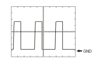
(1) Waveform 1
| Item | Content |
|---|---|
| Tester Connection | A74-16 (NE) - J41-18 (E) |
| Tool Setting | 2 V/DIV., 2 ms./DIV. |
| Condition | Idling (engine warmed up) |
HINT:
The wavelength becomes shorter as the engine speed increases.
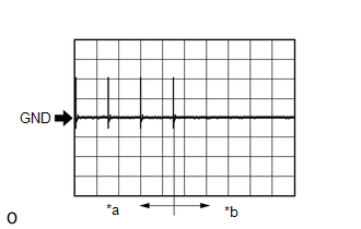
(2) Waveform 2
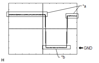
| *a | Steering lock motor not operating |
| *b | Steering lock motor operating |
| Item | Content |
|---|---|
| Tester Connection | J41-25 (SLR+) - J41-18(E) |
| Tool Setting | 2 V/DIV., 200 ms./DIV. |
| Condition | Steering lock motor stopped → Steering lock motor operating → Steering lock motor stopped |
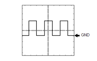
(3) Waveform 3
| Item | Content |
|---|---|
| Tester Connection | J41-19 (SPD) - J41-18(E) |
| Tool Setting | 5 V/DIV., 20 ms./DIV. |
| Condition | Vehicle being driven at approx. 5 km/h (3 mph) |
HINT:
The wavelength becomes shorter as the vehicle speed increases.
(4) Waveform 4
| *a | For 30 seconds after any door closed |
| *b | After 30 seconds or more have elapsed since any door closed |
| Item | Content |
|---|---|
| Tester Connection | J41-8 (CLG5) - J41-18 (E) J41-9 (CG5B) - J41-18 (E) R1-5 (CLG6) - J41-18 (E) R1-6 (CG6B) - J41-18 (E) R1-11 (CLG7) - J41-18 (E) R1-10 (CG7B) - J41-18 (E) |
| Tool Setting | 2 V/DIV., 500 ms/DIV. |
| Condition | Procedure:
|
CHECK STEERING LOCK ECU (STEERING LOCK ACTUATOR OR UPPER BRACKET ASSEMBLY)
Click here .gif)
CHECK ID CODE BOX (IMMOBILISER CODE ECU)
Click here
CHECK ECM
Click here
CHECK ENGINE SWITCH
Click here
 Problem Symptoms Table
PROBLEM SYMPTOMS TABLE HINT:
Use the table below to help determine the cause of problem symptoms. If multiple suspected areas are listed, the potential causes of the symptoms are listed in order of ...
 Diagnosis System
DIAGNOSIS SYSTEM DESCRIPTION (a) Smart access system with push-button start (for Start Function) data and Diagnostic Trouble Codes (DTCs) can be read through the Data Link Connector 3 (DLC3) of the ve ...
Other materials:
Lexus RX (RX 350L, RX450h) 2016-2026 Repair Manual > Footwell Light: Removal
REMOVAL PROCEDURE 1. REMOVE FRONT DOOR SCUFF PLATE LH (for Driver Side) Click here 2. REMOVE COWL SIDE TRIM BOARD LH (for Driver Side) Click here 3. REMOVE NO. 1 INSTRUMENT PANEL UNDER COVER SUB-ASSEMBLY (for Driver Side) Click here 4. REMOVE NO. 1 INTERIOR ILLUMINATION LIGHT ASSEMBLY ...
Lexus RX (RX 350L, RX450h) 2016-2026 Repair Manual > Navigation Antenna: Installation
INSTALLATION PROCEDURE 1. INSTALL NAVIGATION ANTENNA BRACKET 2. INSTALL NAVIGATION ANTENNA ASSEMBLY (a) Engage the 6 guides and 2 claws to install the navigation antenna assembly as shown in the illustration. Install in this Direction 3. INSTALL NAVIGATION ANTENNA ASSEMBLY WITH BRACKET (a) ...
Lexus RX (RX 350L, RX450h) 2016-{YEAR} Owners Manual
- For your information
- Pictorial index
- For safety and security
- Instrument cluster
- Operation of each component
- Driving
- Lexus Display Audio system
- Interior features
- Maintenance and care
- When trouble arises
- Vehicle specifications
- For owners
Lexus RX (RX 350L, RX450h) 2016-{YEAR} Repair Manual

0.0093