Lexus RX (RX 350L, RX450h) 2016-2026 Repair Manual: Engine does not Start
DESCRIPTION
When the electrical key transmitter sub-assembly is in the cabin and the engine switch is pressed, the certification ECU (smart key ECU assembly) receives a signal and changes the power source mode. Additionally, when the shift lever is in P and the brake pedal is depressed, the engine can be started by pressing the engine switch. If the steering is unlocked, the engine can also be started by pressing the engine switch with the shift lever in N and the brake pedal depressed.
Related Data List and Active Test Items| Problem Symptom | Data List and Active Test |
|---|---|
| Engine does not start | Power Source Control
Smart Access
Starting Control
|
WIRING DIAGRAM
CAUTION / NOTICE / HINT
NOTICE:
- When using the Techstream with the engine switch off, connect the Techstream to the DLC3 and turn a courtesy light switch on and off at intervals of 1.5 seconds or less until communication between the Techstream and the vehicle begins. Then select the vehicle type under manual mode and enter the following menus: Body Electrical / Smart Access. While using the Techstream, periodically turn a courtesy light switch on and off at intervals of 1.5 seconds or less to maintain communication between the Techstream and the vehicle.
-
The smart access system with push-button start (for Start Function) uses the LIN communication system and CAN communication system. Inspect the communication function by following How to Proceed with Troubleshooting. Troubleshoot the smart access system with push-button start (for Start Function) after confirming that the communication systems are functioning properly.
Click here
.gif)
-
If the smart access system with push-button start (for Start Function) has been canceled, enable the system before performing troubleshooting.
Click here
- Inspect the fuses of circuits related to this system before performing the following procedure.
-
Before replacing the certification ECU (smart key ECU assembly) or an electrical key transmitter sub-assembly, refer to smart access system with push-button start (for Start Function) Precaution.
Click here
- After completing repairs, confirm that the problem does not recur.
HINT:
- When the cable is disconnected and reconnected to the negative (-) battery terminal, the power source mode returns to the state it was in before the cable was disconnected.
- If the engine switch is turned from on (IG) to on (ACC) with the shift lever in any position other than P, and then the shift lever is moved to P and the engine switch is pressed with the brake pedal depressed, the engine switch will turn off.
- If the brake pedal is repeatedly depressed while the engine is stopped, the brake booster pressure will be released and the force required to depress the brake pedal to illuminate the stop lights will increase.
PROCEDURE
| 1. | CHECK ELECTRICAL KEY TRANSMITTER SUB-ASSEMBLY |
(a) Press a switch of the electrical key transmitter sub-assembly.
OK:
The electrical key transmitter sub-assembly LED illuminates.
| NG | .gif) | GO TO STEP 19 |
|
.gif)
| 2. | READ VALUE USING TECHSTREAM (KEY LOW BATTERY) |
(a) Connect the Techstream to the DLC3.
(b) Turn the engine switch on (IG).
(c) Turn the Techstream on.
(d) Enter the following menus: Body Electrical / Smart Access / Data List.
(e) Read the Data List according to the display on the Techstream.
Body Electrical > Smart Access > Data List| Tester Display | Measurement Item | Range | Normal Condition | Diagnostic Note |
|---|---|---|---|---|
| Key Low Battery | Transmitter battery depleted | No or Yes | No: Transmitter battery not depleted Yes: Transmitter battery depleted | The electrical key transmitter sub-assembly sends voltage information to the certification ECU (smart key ECU assembly) when it is transmitting. "Yes" is displayed for the Data List item "Key Low Battery" when this voltage information indicates 2.2 V or less. This Data List item should be checked when the electrical key transmitter sub-assembly is at room temperature (example: at -20°C (-4°F), "Yes" may be displayed even if the transmitter battery is new). |
| Tester Display |
|---|
| Key Low Battery |
| Result | Proceed to |
|---|---|
| "No" is displayed on the Techstream screen | A |
| "Yes" is displayed on the Techstream screen | B |
| B | | REPLACE TRANSMITTER BATTERY |
|
| 3. | CHECK WAVE ENVIRONMENT |
(a) If the problem occurs in certain locations or times of day, the possibility of wave interference is high.
HINT:
Whether the problem is due to wave interference can be checked by holding the electrical key transmitter sub-assembly near the door control receiver.
OK:
Engine starts.
| OK | | AFFECTED BY WAVE INTERFERENCE |
|
| 4. | CHECK ENGINE SWITCH CONDITION |
(a) Get into the vehicle while carrying an electrical key transmitter sub-assembly.
(b) Move the shift lever to P.
(c) With the brake pedal released, check that pressing the engine switch causes the power source mode to change.
| Result | Proceed to |
|---|---|
| Power source mode changes : Off → on (ACC) → on (IG) → off | A |
| Power source mode does not change to on (ACC) or on (IG) | B |
| Power source mode changes to on (IG) but not to on (ACC) | C |
| Power source mode changes to on (ACC) but not to on (IG) | D |
| B | | GO TO POWER SOURCE MODE DOES NOT CHANGE TO ON (IG AND ACC) |
| C | | GO TO POWER SOURCE MODE DOES NOT CHANGE TO ON (ACC) |
| D | | GO TO POWER SOURCE MODE DOES NOT CHANGE TO ON (IG) |
|
| 5. | READ VALUE USING TECHSTREAM (NEUTRAL SW/ CLUTCH SW, SHIFT POSITION P OR N) |
(a) Connect the Techstream to the DLC3.
(b) Turn the engine switch on (IG).
(c) Turn the Techstream on.
(d) Enter the following menus: Body Electrical / Power Source Control or Starting Control / Data List.
(e) Read the Data List according to the display on the Techstream.
Body Electrical > Power Source Control > Data List| Tester Display | Measurement Item | Range | Normal Condition | Diagnostic Note |
|---|---|---|---|---|
| Neutral SW/ Clutch SW | Shift position (P and N) | OFF or ON | OFF: Shift lever in any position other than P or N ON: Shift lever in P or N |
|
| Tester Display |
|---|
| Neutral SW/ Clutch SW |
| Tester Display | Measurement Item | Range | Normal Condition | Diagnostic Note |
|---|---|---|---|---|
| Shift Position P or N | Park/Neutral position switch status | OFF or ON | OFF: Shift lever not in P or N ON: Shift lever in P or N | When malfunctioning, the engine will not crank. |
| Tester Display |
|---|
| Shift Position P or N |
OK:
The Techstream display changes correctly in response to the shift lever operation.
| NG | | GO TO STEP 25 |
|
| 6. | CHECK FOR DTC |
(a) Using the Techstream, check for certification ECU (smart key ECU assembly) DTCs.
Body Electrical > Smart Access > Trouble Codes Body Electrical > Power Source Control > Trouble Codes Body Electrical > Starting Control > Trouble Codes| Result | Proceed to |
|---|---|
| DTCs are not output | A |
| Smart access system with push-button start (for Start Function) DTCs are output | B |
| B | | GO TO DIAGNOSTIC TROUBLE CODE CHART |
|
| 7. | READ VALUE USING TECHSTREAM (STOP LIGHT SWITCH1) |
(a) Connect the Techstream to the DLC3.
(b) Turn the engine switch on (IG).
(c) Turn the Techstream on.
(d) Enter the following menus: Body Electrical / Power Source Control / Data List.
(e) Read the Data List according to the display on the Techstream.
Body Electrical > Power Source Control > Data List| Tester Display | Measurement Item | Range | Normal Condition | Diagnostic Note |
|---|---|---|---|---|
| Stop Light Switch1 | State of brake pedal | OFF or ON | OFF: Brake pedal released ON: Brake pedal depressed |
|
| Tester Display |
|---|
| Stop Light Switch1 |
OK:
The Techstream display changes correctly in response to the brake pedal operation.
| NG | | GO TO STEP 22 |
|
| 8. | READ VALUE USING TECHSTREAM (STARTER REQUEST SIGNAL) |
(a) Connect the Techstream to the DLC3.
(b) Turn the engine switch on (IG).
(c) Turn the Techstream on.
(d) Enter the following menus: Body Electrical / Power Source Control / Data List.
(e) Read the Data List according to the display on the Techstream.
Body Electrical > Power Source Control > Data List| Tester Display | Measurement Item | Range | Normal Condition | Diagnostic Note |
|---|---|---|---|---|
| Starter Request Signal | Engine start request signal status | OFF or ON | OFF: The engine switch is not pressed ON: With the shift lever in P and the brake pedal depressed, the engine switch is pressed and held |
|
| Tester Display |
|---|
| Starter Request Signal |
NOTICE:
Check that the key indicator display is displayed on the multi-information display in the combination meter assembly, and then press the engine switch.
OK:
The Techstream display changes correctly in response to the engine switch operation.
| NG | | GO TO STEP 20 |
|
| 9. | INSPECT ST RELAY |
(a) Inspect the ST relay.
Click here
| NG | | REPLACE ST RELAY (STARTER RELAY ASSEMBLY) |
|
| 10. | INSPECT STARTER ASSEMBLY |
(a) Remove the starter assembly.
Click here
(b) Inspect the starter assembly.
Click here
| NG | | REPLACE STARTER ASSEMBLY |
|
| 11. | CHECK HARNESS AND CONNECTOR (BATTERY - STARTER ASSEMBLY AND ST RELAY) |
(a) Measure the voltage according to the value(s) in the table below.
Standard Voltage:
| Tester Connection | Condition | Specified Condition |
|---|---|---|
| D71-1 (B) - Body ground | Always | 11 to 14 V |
| 5 (ST relay) - Body ground | Always | 11 to 14 V |
| NG | | REPAIR OR REPLACE HARNESS OR CONNECTOR |
|
| 12. | CHECK HARNESS AND CONNECTOR (ST RELAY - BODY GROUND) |
(a) Measure the resistance according to the value(s) in the table below.
Standard Resistance:
| Tester Connection | Condition | Specified Condition |
|---|---|---|
| 1 (ST relay) - Body ground | Always | Below 1 Ω |
| NG | | REPAIR OR REPLACE HARNESS OR CONNECTOR |
|
| 13. | CHECK HARNESS AND CONNECTOR (STARTER ASSEMBLY - ST RELAY) |
(a) Measure the resistance according to the value(s) in the table below.
Standard Resistance:
| Tester Connection | Condition | Specified Condition |
|---|---|---|
| 3 (ST relay) - D21-1 (ST) | Always | Below 1 Ω |
| 3 (ST relay) or D21-1 (ST) - Body ground | Always | 10 kΩ or higher |
| NG | | REPAIR OR REPLACE HARNESS OR CONNECTOR |
|
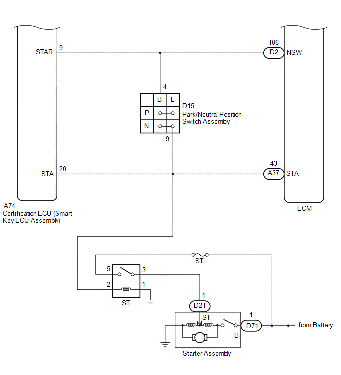
| 14. | CHECK CERTIFICATION ECU (SMART KEY ECU ASSEMBLY) |
| (a) Measure the voltage according to the value(s) in the table below. Standard Voltage:
HINT: *: While the engine is cranking, the battery voltage may drop to approximately 6 V. |
|
| NG | | REPLACE CERTIFICATION ECU (SMART KEY ECU ASSEMBLY) |
|
| 15. | CHECK HARNESS AND CONNECTOR (CERTIFICATION ECU (SMART KEY ECU ASSEMBLY) - ST RELAY) |
(a) Disconnect the A74 certification ECU (smart key ECU assembly) connector.
(b) Measure the resistance according to the value(s) in the table below.
Standard Resistance:
| Tester Connection | Condition | Specified Condition |
|---|---|---|
| A74-20 (STA) - 2 (ST relay) | Always | Below 1 Ω |
| A74-20 (STA) or 2 (ST relay) - Body ground | Always | 10 kΩ or higher |
| NG | | REPAIR OR REPLACE HARNESS OR CONNECTOR |
|
| 16. | CHECK CERTIFICATION ECU (SMART KEY ECU ASSEMBLY) |
| (a) Reconnect the A74 certification ECU (smart key ECU assembly) connector. |
|
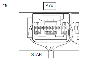
(b) Measure the voltage according to the value(s) in the table below.
Standard Voltage:
| Tester Connection | Condition | Specified Condition |
|---|---|---|
| A74-9 (STAR) - Body ground | Engine switch pressed and held with brake pedal depressed (starter on) → Approximately 1 second after engine switch released (starter off) | 6 V or higher* → 1.0 V or less |
HINT:
*: While the engine is cranking, the battery voltage may drop to approximately 6 V.
| NG | | REPLACE CERTIFICATION ECU (SMART KEY ECU ASSEMBLY) |
|
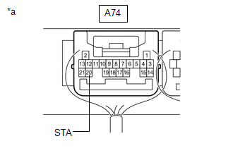
| 17. | CHECK HARNESS AND CONNECTOR (CERTIFICATION ECU (SMART KEY ECU ASSEMBLY) - PARK/NEUTRAL POSITION SWITCH ASSEMBLY) |
(a) Disconnect the A74 certification ECU (smart key ECU assembly) connector.
(b) Disconnect the D15 park/neutral position switch assembly connector.
(c) Measure the resistance according to the value(s) in the table below.
Standard Resistance:
| Tester Connection | Condition | Specified Condition |
|---|---|---|
| A74-9 (STAR) - D15-4 (B) | Always | Below 1 Ω |
| A74-9 (STAR) or D15-4 (B) - Body ground | Always | 10 kΩ or higher |
| NG | | REPAIR OR REPLACE HARNESS OR CONNECTOR |
|
| 18. | CHECK HARNESS AND CONNECTOR (PARK/NEUTRAL POSITION SWITCH ASSEMBLY - ST RELAY (STARTER RELAY ASSEMBLY) |
(a) Measure the resistance according to the value(s) in the table below.
Standard Resistance:
| Tester Connection | Condition | Specified Condition |
|---|---|---|
| D15-9 (L) - 2 (ST relay) | Always | Below 1 Ω |
| D15-9 (L) or 2 (ST relay) - Body ground | Always | 10 kΩ or higher |
| OK | | GO TO SFI SYSTEM |
| NG | | REPAIR OR REPLACE HARNESS OR CONNECTOR |
| 19. | INSPECT TRANSMITTER BATTERY |
(a) Inspect the transmitter battery.
Click here
NOTICE:
Do not wrap the lead wire ground a terminal, wedge it between terminals, or solder it. The terminal may be deformed or damaged, and the transmitter battery will not be able to be installed correctly.
| OK | | REPLACE ELECTRICAL KEY TRANSMITTER SUB-ASSEMBLY |
| NG | | REPLACE TRANSMITTER BATTERY |
| 20. | CHECK STEERING LOCK |
(a) Check that the steering unlocks when the engine switch is turned on (ACC).
OK:
The steering unlocks.
| NG | | GO TO STEERING LOCK SYSTEM (UNABLE TO UNLOCK STEERING) |
|
| 21. | CHECK SECURITY INDICATOR LIGHT (IMMOBILISER SYSTEM UNSET) |
(a) Get into the vehicle while carrying an electrical key transmitter sub-assembly.
(b) Move the shift lever to P.
(c) Press the engine switch with the brake pedal released and check that the security indicator light changes from blinking to off at the same time that the power source mode changes to on (ACC).
HINT:
The immobiliser function can be determined to be operating correctly if the security indicator light changes from blinking to off at the same time that the power source mode changes to on (ACC).
OK:
The security indicator light changes from blinking to off at the same time that the power source mode changes to on (ACC).
| OK | | REPLACE CERTIFICATION ECU (SMART KEY ECU ASSEMBLY) |
| NG | | GO TO IMMOBILISER SYSTEM (PROBLEM SYMPTOMS TABLE) |
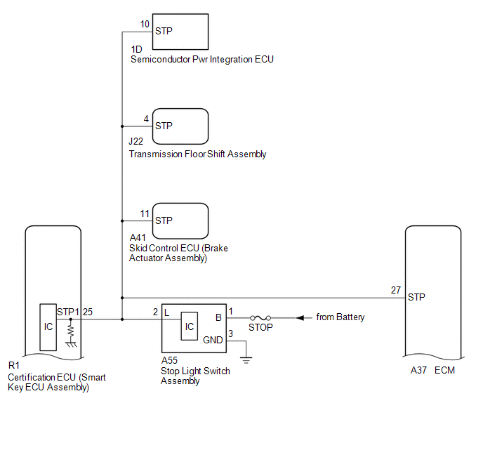
| 22. | CHECK HARNESS AND CONNECTOR (CERTIFICATION ECU (SMART KEY ECU ASSEMBLY) - POWER SUPPLY AND BODY GROUND) |
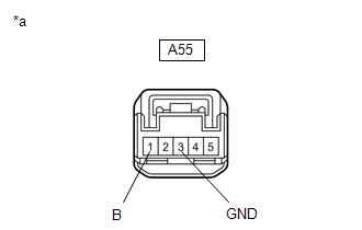
| (a) Disconnect the A55 stop light switch assembly connector. |
|
(b) Measure the voltage according to the value(s) in the table below.
Standard Voltage:
| Tester Connection | Condition | Specified Condition |
|---|---|---|
| A55-1 (B) - Body ground | Always | 11 to 14 V |
(c) Measure the resistance according to the value(s) in the table below.
Standard Resistance:
| Tester Connection | Condition | Specified Condition |
|---|---|---|
| A55-3 (GND) - Body ground | Always | Below 1 Ω |
| NG | | REPAIR OR REPLACE HARNESS OR CONNECTOR |
|
| 23. | CHECK HARNESS AND CONNECTOR (CERTIFICATION ECU (SMART KEY ECU ASSEMBLY) - STOP LIGHT SWITCH ASSEMBLY) |
(a) Disconnect the R1 certification ECU (smart key ECU assembly) connector.
(b) Disconnect the A37 ECM connector.
(c) Disconnect the A41 skid control ECU (brake actuator assembly) connector.
(d) Disconnect the J22 transmission floor shift assembly connector.
(e) Disconnect the 1D semiconductor pwr integration ECU connector.
(f) Measure the resistance according to the value(s) in the table below.
Standard Resistance:
| Tester Connection | Condition | Specified Condition |
|---|---|---|
| R1-25 (STP1) - A55-2 (L) | Always | Below 1 Ω |
| R1-25 (STP1) or A55-2 (L) - Body ground | Always | 10 kΩ or higher |
| NG | | REPAIR OR REPLACE HARNESS OR CONNECTOR |
|
| 24. | INSPECT STOP LIGHT SWITCH ASSEMBLY |
(a) Inspect the stop light switch assembly.
Click here
| OK | | REPLACE CERTIFICATION ECU (SMART KEY ECU ASSEMBLY) |
| NG | | REPLACE STOP LIGHT SWITCH ASSEMBLY |
| 25. | INSPECT PARK/NEUTRAL POSITION SWITCH ASSEMBLY |
(a) Remove the park/neutral position switch assembly.
Click here
(b) Inspect the park/neutral position switch assembly.
Click here
| NG | | REPLACE PARK/NEUTRAL POSITION SWITCH ASSEMBLY |
|
| 26. | CHECK HARNESS AND CONNECTOR (CERTIFICATION ECU (SMART KEY ECU ASSEMBLY) - PARK/NEUTRAL POSITION SWITCH ASSEMBLY) |
(a) Disconnect the A74 certification ECU (smart key ECU assembly) connector.
(b) Measure the resistance according to the value(s) in the table below.
Standard Resistance:
| Tester Connection | Condition | Specified Condition |
|---|---|---|
| A74-9 (STAR) - D15-4 (B) | Always | Below 1 Ω |
| A74-9 (STAR) or D15-4 (B) - Body ground | Always | 10 kΩ or higher |
| OK | | REPLACE CERTIFICATION ECU (SMART KEY ECU ASSEMBLY) |
| NG | | REPAIR OR REPLACE HARNESS OR CONNECTOR |
 Lost Communication with ECM / PCM (U0100,U0140,U0142,U0155,U1117)
DESCRIPTION These DTCs are stored when there is a CAN communication malfunction between the certification ECU (smart key ECU assembly), ECM, main body ECU (multiplex network body ECU) or combination m ...
 Power Source Mode does not Change to ON (IG and ACC)
DESCRIPTION If any of the following operations are performed, the certification ECU (smart key ECU assembly) receives a signal, and changes the power source mode.
With the electrical key transmitte ...
Other materials:
Lexus RX (RX 350L, RX450h) 2016-2026 Repair Manual > Navigation System: Visual Mute Signal Circuit between Radio Receiver and Multi-display
DESCRIPTION The radio receiver assembly sends a visual mute signal to the multi-display assembly. As a result, a black screen is displayed when the screen changes so that noise and distorted images are not displayed. When an open exists in the circuit, noise and distorted images will be displayed in ...
Lexus RX (RX 350L, RX450h) 2016-2026 Repair Manual > Automatic Transaxle Assembly: Components
COMPONENTS ILLUSTRATION *1 OUTER COWL TOP PANEL SUB-ASSEMBLY - - N*m (kgf*cm, ft.*lbf): Specified torque - - ILLUSTRATION *1 FRONT WHEEL OPENING EXTENSION PAD LH *2 NO. 3 ENGINE UNDER COVER *3 FRONT FENDER APRON SEAL LH - - ILLUSTRATION *1 FRONT L ...
Lexus RX (RX 350L, RX450h) 2016-{YEAR} Owners Manual
- For your information
- Pictorial index
- For safety and security
- Instrument cluster
- Operation of each component
- Driving
- Lexus Display Audio system
- Interior features
- Maintenance and care
- When trouble arises
- Vehicle specifications
- For owners
Lexus RX (RX 350L, RX450h) 2016-{YEAR} Repair Manual

0.0202