Lexus RX (RX 350L, RX450h) 2016-2026 Repair Manual: Removal
REMOVAL
CAUTION / NOTICE / HINT
The necessary procedures (adjustment, calibration, initialization, or registration) that must be performed after parts are removed and installed, or replaced during radio receiver assembly removal/installation are shown below.
Necessary Procedures After Parts Removed/Installed/Replaced| Replaced Part or Performed Procedure | Necessary Procedure | Effect/Inoperative Function when Necessary Procedure not Performed | Link |
|---|---|---|---|
| Disconnect cable from negative battery terminal | Memorize steering angle neutral point | Lane Control System | |
| Pre-collision System | |||
| Intelligent Clearance Sonar System*1 | |||
| Parking Assist Monitor System | | ||
| Panoramic View Monitor System | | ||
| Lighting System (w/ Automatic Headlight Beam Level Control System) | | ||
| Initialize back door lock | Power Door Lock Control System | | |
| Reset back door close position | Power Back Door System (w/ Outside Door Control Switch) | |
*1: When performing learning using the Techstream.
Click here .gif)
PROCEDURE
1. PRECAUTION
NOTICE:
After turning the engine switch off, waiting time may be required before disconnecting the cable from the negative (-) battery terminal. Therefore, make sure to read the disconnecting the cable from the negative (-) battery terminal notices before proceeding with work.
Click here
(a) for Audio and Visual System:
(1) for 8 Inch Display:
Click here
(2) for 12.3 Inch Display:
NOTICE:
-
When performing the following work, the audio and visual system may restart when turning the engine switch on (ACC) (due to radio receiver assembly and navigation ECU certification).
- Repair or replace the negative (-) battery terminal due to it being disconnected or depleted.
- The radio receiver assembly or navigation ECU replacement or removal and installation.
- After replacing the radio receiver assembly, if "New software is not compatible with the system. Contact your dealer." is displayed on the multi-display assembly, update the software of the navigation ECU.
NOTICE:
Click here
(b) for Navigation System:
NOTICE:
-
When performing the following work, the navigation system may restart when turning the engine switch on (ACC) (due to radio receiver assembly and navigation ECU certification).
- Repair or replace the negative (-) battery terminal due to it being disconnected or depleted.
- The radio receiver assembly or navigation ECU replacement or removal and installation.
- After replacing the radio receiver assembly, if the "New software is not compatible with the system. Contact your dealer." on-screen message is displayed on the multi-display assembly, update the software of the navigation ECU.
NOTICE:
Click here
2. DISCONNECT CABLE FROM NEGATIVE BATTERY TERMINAL
NOTICE:
When disconnecting the cable, some systems need to be initialized after the cable is reconnected.
Click here
3. REMOVE LOWER NO. 2 INSTRUMENT PANEL FINISH PANEL
Click here
4. REMOVE LOWER NO. 1 INSTRUMENT PANEL FINISH PANEL
Click here
5. REMOVE INSTRUMENT CLUSTER FINISH PANEL ORNAMENT
Click here
6. REMOVE LOWER INSTRUMENT FINISH PANEL SUB
Click here
7. REMOVE RADIO RECEIVER ASSEMBLY WITH REGISTER
| (a) Remove the 2 bolts. |
|
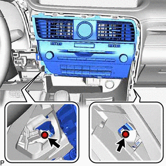
(b) Pull the radio receiver assembly with register toward the rear of the vehicle to disengage the 7 clips.
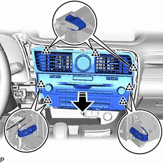
.png) | Remove in this Direction |
(c) Disconnect each connector and remove the radio receiver assembly with register.
8. REMOVE CLOCK ASSEMBLY
Click here
9. REMOVE NO. 1 NAVIGATION WIRE (w/ Navigation ECU)
Click here
10. REMOVE NO. 3 INSTRUMENT PANEL REGISTER ASSEMBLY
(a) Using a screwdriver, disengage the 4 claws and remove the No. 3 instrument panel register assembly as shown in the illustration.
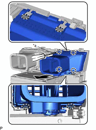
| *a | Protective Tape |
.png) | Insert Screwdriver Here |
| | Remove in this Direction |
HINT:
Tape the screwdriver tip before use.
11. REMOVE NO. 4 INSTRUMENT PANEL REGISTER ASSEMBLY
HINT:
Use the same procedure as for the No. 3 instrument panel register assembly.
12. REMOVE NO. 1 RADIO BRACKET
(a) w/o Navigation ECU:
| (1) Remove the 3 screws and No. 1 radio bracket. |
|
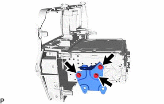
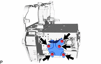
(b) w/ Navigation ECU:
| (1) Remove the 5 screws and No. 1 radio bracket. |
|
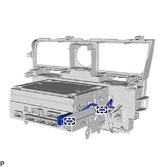
13. REMOVE NO. 2 RADIO BRACKET
| (a) Disengage the 2 clamps. |
|
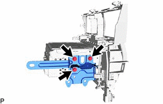
(b) w/o Navigation ECU:
| (1) Remove the 3 screws and No. 2 radio bracket. |
|
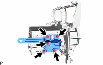
(c) w/ Navigation ECU:
| (1) Remove the 5 screws and No. 2 radio bracket. |
|
14. REMOVE NAVIGATION ECU (w/ Navigation ECU)
15. REMOVE RADIO RECEIVER ASSEMBLY
 Installation
INSTALLATION PROCEDURE 1. INSTALL RADIO RECEIVER ASSEMBLY 2. INSTALL NAVIGATION ECU (w/ Navigation ECU) 3. INSTALL NO. 2 RADIO BRACKET (a) w/o Navigation ECU: (1) Install the No. 2 radio bracket with ...

Other materials:
Lexus RX (RX 350L, RX450h) 2016-2026 Repair Manual > Smart Access System With Push-button Start (for Entry Function): Open in Outside Luggage Compartment Electrical Key Antenna Circuit (B27A8)
DESCRIPTION The certification ECU (smart key ECU assembly) generates a request signal and transmits the signal to the electrical key antenna (outside luggage compartment). For the electrical key antenna (outside luggage compartment) to detect when the electrical key transmitter sub-assembly is broug ...
Lexus RX (RX 350L, RX450h) 2016-2026 Repair Manual > Power Tilt And Power Telescopic Steering Column System: Problem Symptoms Table
PROBLEM SYMPTOMS TABLE HINT:
Use the table below to help determine the cause of problem symptoms. If multiple suspected areas are listed, the potential causes of the symptoms are listed in order of probability in the "Suspected Area" column of the table.
Check each system by checking the suspec ...
Lexus RX (RX 350L, RX450h) 2016-{YEAR} Owners Manual
- For your information
- Pictorial index
- For safety and security
- Instrument cluster
- Operation of each component
- Driving
- Lexus Display Audio system
- Interior features
- Maintenance and care
- When trouble arises
- Vehicle specifications
- For owners
Lexus RX (RX 350L, RX450h) 2016-{YEAR} Repair Manual

0.0166