Lexus RX (RX 350L, RX450h) 2016-2026 Repair Manual: Removal
REMOVAL
PROCEDURE
1. REMOVE CONSOLE BOX ASSEMBLY
Click here .gif)
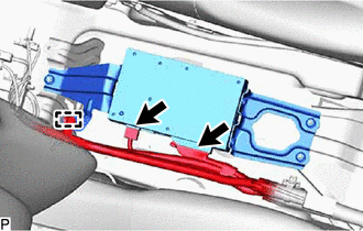
2. REMOVE STEREO COMPONENT AMPLIFIER ASSEMBLY WITH BRACKET (for TMMC Made)
| (a) Disconnect each connector. |
|
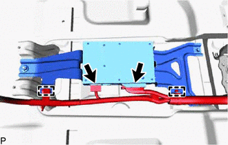
(b) Disengage the 2 clamps.
(c) Remove the 2 bolts, nut and stereo component amplifier assembly with bracket.
 | Bolt |
.png) | Nut |
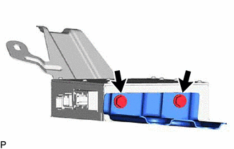
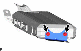
3. REMOVE NO. 1 AMPLIFIER BRACKET (for TMMC Made)
(a) except 15 Speakers:
| (1) Remove the 2 screws and No. 1 amplifier bracket. |
|

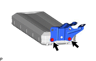
(b) for 15 Speakers:
| (1) Remove the 2 screws and No. 1 amplifier bracket. |
|
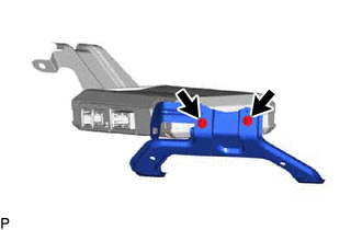
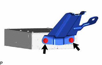
4. REMOVE NO. 2 AMPLIFIER BRACKET (for TMMC Made)
(a) except 15 Speakers:
| (1) Remove the 2 screws and No. 2 amplifier bracket. |
|
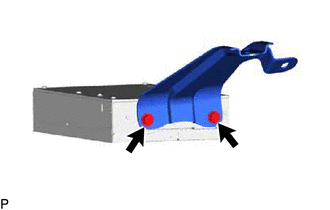
(b) for 15 Speakers:
| (1) Remove the 2 screws and No. 2 amplifier bracket. |
|
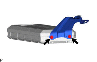
5. REMOVE STEREO COMPONENT AMPLIFIER ASSEMBLY (for TMMC Made)
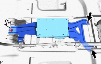
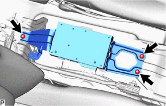
6. REMOVE STEREO COMPONENT AMPLIFIER ASSEMBLY WITH BRACKET (for TMC Made)
| (a) Disconnect each connector. |
|
(b) Disengage the clamp.
| (c) Remove the 3 nuts and remove the stereo component amplifier assembly with bracket. |
|
7. REMOVE NO. 1 AMPLIFIER BRACKET (for TMC Made)
(a) except 15 Speakers:
| (1) Remove the 2 screws and No. 1 amplifier bracket. |
|
(b) for 15 Speakers:
| (1) Remove the 2 screws and No. 1 amplifier bracket. |
|
8. REMOVE NO. 2 AMPLIFIER BRACKET (for TMC Made)
(a) except 15 Speakers:
| (1) Remove the 2 screws and No. 2 amplifier bracket. |
|
(b) for 15 Speakers:
| (1) Remove the 2 screws and No. 2 amplifier bracket. |
|
9. REMOVE STEREO COMPONENT AMPLIFIER ASSEMBLY (for TMC Made)
 Installation
INSTALLATION PROCEDURE 1. INSTALL STEREO COMPONENT AMPLIFIER ASSEMBLY 2. INSTALL NO. 2 AMPLIFIER BRACKET (a) Install the No. 2 amplifier bracket with the 2 screws. 3. INSTALL NO. 1 AMPLIFIER BRACKET ( ...
 Stereo Jack Adapter Assembly (for Console Box Front Side)
ComponentsCOMPONENTS ILLUSTRATION *1 CONSOLE PANEL SUB-ASSEMBLY *2 INSTRUMENT CLUSTER FINISH PANEL ORNAMENT *3 LOWER NO. 1 INSTRUMENT PANEL FINISH PANEL *4 LOWER NO. 2 INSTRUMENT P ...
Other materials:
Lexus RX (RX 350L, RX450h) 2016-2026 Repair Manual > Transfer Assembly: Components
COMPONENTS ILLUSTRATION *1 AUTOMATIC TRANSMISSION ASSEMBLY *2 TRANSFER AND TRANSAXLE SETTING STUD BOLT *3 TRANSFER ASSEMBLY - - N*m (kgf*cm, ft.*lbf): Specified torque ● Non-reusable part ★ Precoated part - - ILLUSTRATION *1 TRANSFER AND TRANSAXL ...
Lexus RX (RX 350L, RX450h) 2016-2026 Repair Manual > Lighting System: How To Proceed With Troubleshooting
CAUTION / NOTICE / HINT HINT:
Use the following procedure to troubleshoot the lighting system.
*: Use the Techstream.
PROCEDURE 1. VEHICLE BROUGHT TO WORKSHOP
NEXT 2. CUSTOMER PROBLEM ANALYSIS AND SYMPTOM CHECK
NEXT 3. INSPECT BATTERY ...
Lexus RX (RX 350L, RX450h) 2016-{YEAR} Owners Manual
- For your information
- Pictorial index
- For safety and security
- Instrument cluster
- Operation of each component
- Driving
- Lexus Display Audio system
- Interior features
- Maintenance and care
- When trouble arises
- Vehicle specifications
- For owners
Lexus RX (RX 350L, RX450h) 2016-{YEAR} Repair Manual

0.0116