Lexus RX (RX 350L, RX450h) 2016-2026 Repair Manual: Stereo Jack Adapter Assembly (for Console Box Front Side)
Components
COMPONENTS
ILLUSTRATION
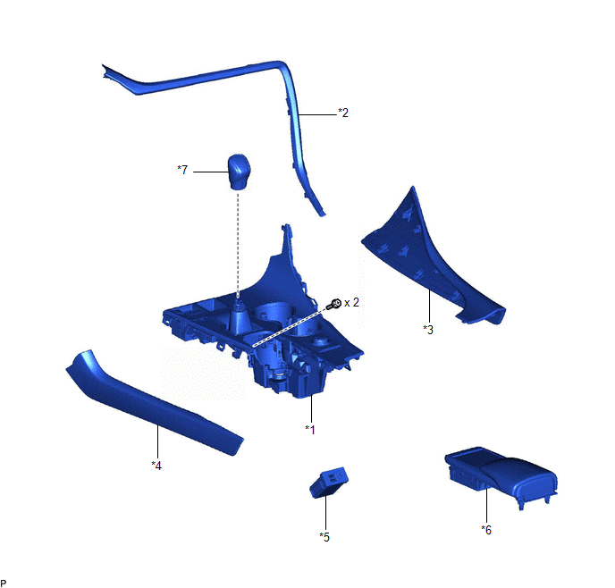
| *1 | CONSOLE PANEL SUB-ASSEMBLY | *2 | INSTRUMENT CLUSTER FINISH PANEL ORNAMENT |
| *3 | LOWER NO. 1 INSTRUMENT PANEL FINISH PANEL | *4 | LOWER NO. 2 INSTRUMENT PANEL FINISH PANEL |
| *5 | NO. 1 STEREO JACK ADAPTER ASSEMBLY | *6 | REAR CONSOLE UPPER PANEL |
| *7 | SHIFT LEVER KNOB SUB-ASSEMBLY | - | - |
Removal
REMOVAL
PROCEDURE
1. REMOVE REAR CONSOLE UPPER PANEL
Click here .gif)
2. REMOVE LOWER NO. 2 INSTRUMENT PANEL FINISH PANEL
Click here
3. REMOVE LOWER NO. 1 INSTRUMENT PANEL FINISH PANEL
Click here
4. REMOVE SHIFT LEVER KNOB SUB-ASSEMBLY
Click here
5. REMOVE INSTRUMENT CLUSTER FINISH PANEL ORNAMENT
Click here
6. REMOVE CONSOLE PANEL SUB-ASSEMBLY
Click here
7. REMOVE NO. 1 STEREO JACK ADAPTER ASSEMBLY
(a) Disconnect the 2 connectors.
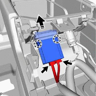
.png) | Remove in this Direction |
(b) Disengage the 2 claws and remove the No. 1 stereo jack adapter assembly as shown in the illustration.
Installation
INSTALLATION
PROCEDURE
1. INSTALL NO. 1 STEREO JACK ADAPTER ASSEMBLY
(a) Engage the 2 claws to install the No. 1 stereo jack adapter assembly as shown in the illustration.
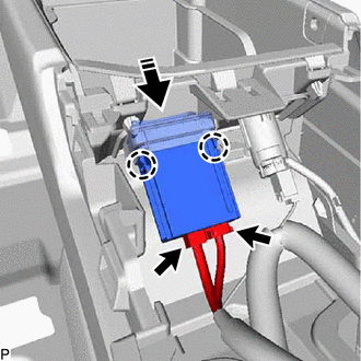
.png) | Install in this Direction |
(b) Connect the 2 connectors.
2. INSTALL CONSOLE PANEL SUB-ASSEMBLY
Click here .gif)
3. INSTALL INSTRUMENT CLUSTER FINISH PANEL ORNAMENT
Click here
4. INSTALL SHIFT LEVER KNOB SUB-ASSEMBLY
Click here
5. INSTALL LOWER NO. 1 INSTRUMENT PANEL FINISH PANEL
Click here
6. INSTALL LOWER NO. 2 INSTRUMENT PANEL FINISH PANEL
Click here
7. INSTALL REAR CONSOLE UPPER PANEL
Click here
 Removal
REMOVAL PROCEDURE 1. REMOVE CONSOLE BOX ASSEMBLY Click here 2. REMOVE STEREO COMPONENT AMPLIFIER ASSEMBLY WITH BRACKET (for TMMC Made) (a) Disconnect each connector. (b) Disengage the ...
 Window Glass Antenna Wire
On-vehicle InspectionON-VEHICLE INSPECTION PROCEDURE 1. INSPECT WINDOW GLASS ANTENNA WIRE (a) Check the continuity of the antenna. HINT: Check for continuity at the center of each antenna wire as s ...
Other materials:
Lexus RX (RX 350L, RX450h) 2016-2026 Owners Manual > Intelligent Clearance Sonar
(ICS): Rear Cross Traffic Auto Brake function (if equipped)
If the Rear Cross Traffic Auto Brake function detects that a collision with
an
approaching vehicle is possible, the hybrid system output will be restricted to
restrain any increase in vehicle speed. (Hybrid system output restriction
control:
See A below.)
Additionally, if the accelerator ped ...
Lexus RX (RX 350L, RX450h) 2016-2026 Repair Manual > Audio And Visual System (for 12.3 Inch Display): Speaker Output Short (B15C3)
DESCRIPTION This DTC is stored when a malfunction occurs in the speakers. DTC No. Detection Item DTC Detection Condition Trouble Area B15C3 Speaker Output Short A short is detected in the speaker output circuit
Harness or connector
Speaker
Stereo component amplifier assembl ...
Lexus RX (RX 350L, RX450h) 2016-{YEAR} Owners Manual
- For your information
- Pictorial index
- For safety and security
- Instrument cluster
- Operation of each component
- Driving
- Lexus Display Audio system
- Interior features
- Maintenance and care
- When trouble arises
- Vehicle specifications
- For owners
Lexus RX (RX 350L, RX450h) 2016-{YEAR} Repair Manual

0.0153