Lexus RX (RX 350L, RX450h) 2016-2026 Repair Manual: Speaker Output Short (B15C3)
DESCRIPTION
This DTC is stored when a malfunction occurs in the speakers.
| DTC No. | Detection Item | DTC Detection Condition | Trouble Area |
|---|---|---|---|
| B15C3 | Speaker Output Short | A short is detected in the speaker output circuit |
|
WIRING DIAGRAM
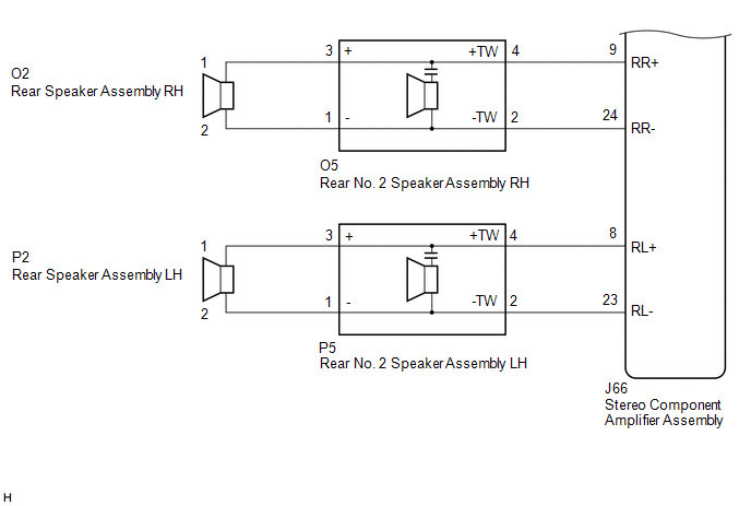
for 9 Speakers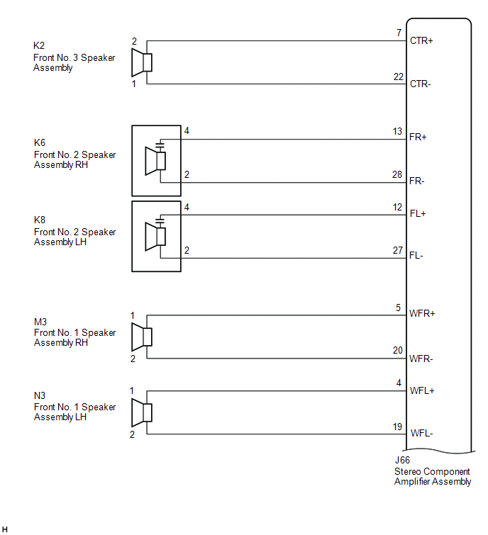
 for 12 Speakers
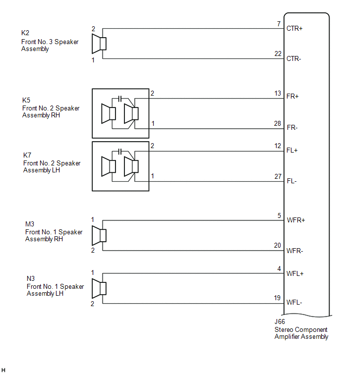
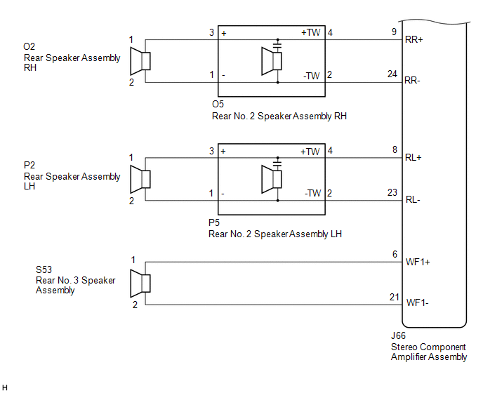 for 15 Speakers
 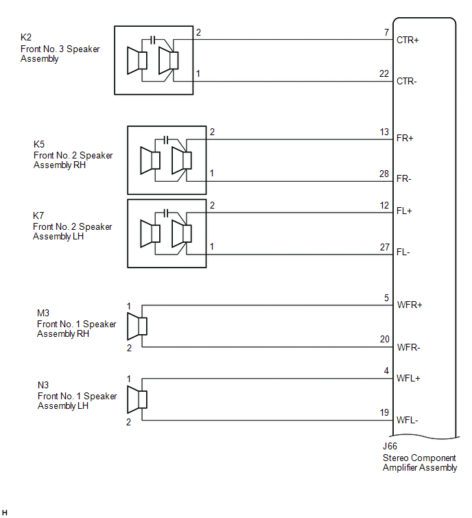 for 15 Speakers
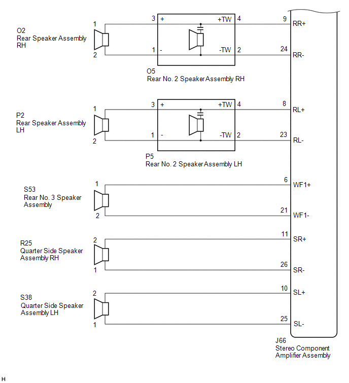
CAUTION / NOTICE / HINT
NOTICE:
Depending on the parts that are replaced during vehicle inspection or maintenance, performing initialization, registration or calibration may be needed. Refer to Precaution for Audio and Visual System.
Click here .gif)
PROCEDURE
| 1. | CHECK HARNESS AND CONNECTOR (STEREO COMPONENT AMPLIFIER ASSEMBLY OR SPEAKERS - BODY GROUND) |
(a) Disconnect the J66 stereo component amplifier assembly connector.
(b) Disconnect the K2 front No. 3 speaker assembly connector.
(c) Disconnect the K6 and K8 front No. 2 speaker assembly connectors (for 9 Speakers).
Disconnect the K5 and K7 front No. 2 speaker assembly connectors (except 9 Speakers).
(d) Disconnect the M3 and N3 front No. 1 speaker assembly connectors.
(e) Disconnect the O5 and P5 rear No. 2 speaker assembly connectors.
(f) Disconnect the S53 rear No. 3 speaker assembly connector (except 9 Speakers).
(g) Disconnect the R25 and S38 quarter side speaker assembly connectors (for 15 Speakers).
(h) Measure the resistance between the stereo component amplifier assembly or the speakers and body ground to check for a short in the wire harness.
Standard Resistance:
| Tester Connection | Condition | Specified Condition |
|---|---|---|
| J66-7 (CTR+) or K2-2 - Body ground | Always | 10 kΩ or higher |
| J66-22 (CTR-) or K2-1 - Body ground | Always | 10 kΩ or higher |
| J66-13 (FR+) or K6-4 - Body ground*1 J66-13 (FR+) or K5-2 - Body ground*2 | Always | 10 kΩ or higher |
| J66-28 (FR-) or K6-2 - Body ground*1 J66-28 (FR-) or K5-1 - Body ground*2 | Always | 10 kΩ or higher |
| J66-12 (FL+) or K8-4 - Body ground*1 J66-12 (FL+) or K7-2 - Body ground*2 | Always | 10 kΩ or higher |
| J66-27 (FL-) or K8-2 - Body ground*1 J66-27 (FL-) or K7-1 - Body ground*2 | Always | 10 kΩ or higher |
| J66-5 (WFR+) or M3-1 - Body ground | Always | 10 kΩ or higher |
| J66-20 (WFR-) or M3-2 - Body ground | Always | 10 kΩ or higher |
| J66-4 (WFL+) or N3-1 - Body ground | Always | 10 kΩ or higher |
| J66-19 (WFL-) or N3-2 - Body ground | Always | 10 kΩ or higher |
| J66-9 (RR+) or O5-4 (+TW) - Body ground | Always | 10 kΩ or higher |
| J66-24 (RR-) or O5-2 (-TW) - Body ground | Always | 10 kΩ or higher |
| J66-8 (RL+) or P5-4 (+TW) - Body ground | Always | 10 kΩ or higher |
| J66-23 (RL-) or P5-2 (-TW) - Body ground | Always | 10 kΩ or higher |
| J66-6 (WF1+) or S53-1 - Body ground*2 | Always | 10 kΩ or higher |
| J66-21 (WF1-) or S53-2 - Body ground*2 | Always | 10 kΩ or higher |
| J66-11 (SR+) or R25-2 - Body ground*3 | Always | 10 kΩ or higher |
| J66-26 (SR-) or R25-1 - Body ground*3 | Always | 10 kΩ or higher |
| J66-10 (SL+) or S38-2 - Body ground*3 | Always | 10 kΩ or higher |
| J66-25 (SL-) or S38-1 - Body ground*3 | Always | 10 kΩ or higher |
- *1: for 9 Speakers
- *2: except 9 Speakers
- *3: for 15 Speakers
| NG | .gif) | REPAIR OR REPLACE HARNESS OR CONNECTOR |
|
.gif)
| 2. | CHECK HARNESS AND CONNECTOR (REAR SPEAKER ASSEMBLY OR REAR NO. 2 SPEAKER ASSEMBLY - BODY GROUND) |
(a) Disconnect the O2 and P2 rear speaker assembly connectors.
(b) Disconnect the O5 and P5 rear No. 2 speaker assembly connectors.
(c) Measure the resistance between the rear speaker assembly or the rear No. 2 speaker assembly and body ground to check for a short in the wire harness.
Standard Resistance:
| Tester Connection | Condition | Specified Condition |
|---|---|---|
| O2-1 or O5-3 (+) - Body ground | Always | 10 kΩ or higher |
| O2-2 or O5-1 (-) - Body ground | Always | 10 kΩ or higher |
| P2-1 or P5-3 (+) - Body ground | Always | 10 kΩ or higher |
| P2-2 or P5-1 (-) - Body ground | Always | 10 kΩ or higher |
| NG | | REPAIR OR REPLACE HARNESS OR CONNECTOR |
|
| 3. | CHECK MODEL |
(a) Choose the model to be inspected.
| Result | Proceed to |
|---|---|
| except 15 Speakers | A |
| for 15 Speakers | B |
| B | | GO TO STEP 5 |
|
| 4. | INSPECT FRONT NO. 3 SPEAKER ASSEMBLY |
(a) Remove the front No. 3 speaker assembly.
Click here
(b) Inspect the front No. 3 speaker assembly.
Click here
| OK | | GO TO STEP 6 |
| NG | | REPLACE FRONT NO. 3 SPEAKER ASSEMBLY |
| 5. | INSPECT FRONT NO. 3 SPEAKER ASSEMBLY |
(a) Remove the front No. 3 speaker assembly.
Click here
(b) Inspect the front No. 3 speaker assembly.
Click here
(c) Clear the DTCs.
Body Electrical > Navigation System > Clear DTCs(d) Recheck for DTCs and check that no DTCs are output.
Body Electrical > Navigation System > Trouble CodesOK:
No DTCs are output.
| OK | | END |
|
| 6. | INSPECT FRONT NO. 2 SPEAKER ASSEMBLY |
(a) Remove the front No. 2 speaker assembly.
Click here
(b) Inspect the front No. 2 speaker assembly.
Click here
(c) Clear the DTCs.
Body Electrical > Navigation System > Clear DTCs(d) Recheck for DTCs and check that no DTCs are output.
Body Electrical > Navigation System > Trouble CodesOK:
No DTCs are output.
| OK | | END |
|
| 7. | INSPECT FRONT NO. 1 SPEAKER ASSEMBLY |
(a) Remove the front No. 1 speaker assembly.
Click here
(b) Inspect the front No. 1 speaker assembly.
Click here
| NG | | REPLACE FRONT NO. 1 SPEAKER ASSEMBLY |
|
| 8. | INSPECT REAR SPEAKER ASSEMBLY |
(a) Remove the rear speaker assembly.
Click here
(b) Inspect the rear speaker assembly.
Click here
| Result | Proceed to |
|---|---|
| OK (for 9 Speakers) | A |
| OK (except 9 Speakers) | B |
| NG | C |
| B | | GO TO STEP 10 |
| C | | REPLACE REAR SPEAKER ASSEMBLY |
|
| 9. | INSPECT REAR NO. 2 SPEAKER ASSEMBLY |
(a) Remove the rear No. 2 speaker assembly.
Click here
(b) Inspect the rear No. 2 speaker assembly.
Click here
(c) Clear the DTCs.
Body Electrical > Navigation System > Clear DTCs(d) Recheck for DTCs and check that no DTCs are output.
Body Electrical > Navigation System > Trouble CodesOK:
No DTCs are output.
| OK | | END |
| NG | | REPLACE STEREO COMPONENT AMPLIFIER ASSEMBLY |
| 10. | INSPECT REAR NO. 2 SPEAKER ASSEMBLY |
(a) Remove the rear No. 2 speaker assembly.
Click here
(b) Inspect the rear No. 2 speaker assembly.
Click here
(c) Clear the DTCs.
Body Electrical > Navigation System > Clear DTCs(d) Recheck for DTCs and check that no DTCs are output.
Body Electrical > Navigation System > Trouble CodesOK:
No DTCs are output.
| Result | Proceed to |
|---|---|
| OK | A |
| NG (for 12 Speakers) | B |
| NG (for 15 Speakers) | C |
| A | | END |
| C | | GO TO STEP 12 |
|
| 11. | INSPECT REAR NO. 3 SPEAKER ASSEMBLY |
(a) Remove the rear No. 3 speaker assembly.
w/o Rear No. 2 Seat: Click here
w/ Rear No. 2 Seat: Click here
(b) Inspect the rear No. 3 speaker assembly.
w/o Rear No. 2 Seat: Click here
w/ Rear No. 2 Seat: Click here
| OK | | REPLACE STEREO COMPONENT AMPLIFIER ASSEMBLY |
| NG | | REPLACE REAR NO. 3 SPEAKER ASSEMBLY |
| 12. | INSPECT REAR NO. 3 SPEAKER ASSEMBLY |
(a) Remove the rear No. 3 speaker assembly.
w/o Rear No. 2 Seat: Click here
w/ Rear No. 2 Seat: Click here
(b) Inspect the rear No. 3 speaker assembly.
w/o Rear No. 2 Seat: Click here
w/ Rear No. 2 Seat: Click here
| NG | | REPLACE REAR NO. 3 SPEAKER ASSEMBLY |
|
| 13. | INSPECT QUARTER SIDE SPEAKER ASSEMBLY |
(a) Remove the quarter side speaker assembly.
w/o Rear No. 2 Seat: Click here
w/ Rear No. 2 Seat: Click here
(b) Inspect the quarter side speaker assembly.
w/o Rear No. 2 Seat: Click here
w/ Rear No. 2 Seat: Click here
| OK | | REPLACE STEREO COMPONENT AMPLIFIER ASSEMBLY |
| NG | | REPLACE QUARTER SIDE SPEAKER ASSEMBLY |
 Speed Signal Malfunction (B15C2)
DESCRIPTION The navigation ECU receives a vehicle speed signal from the combination meter assembly and information from the navigation antenna, and then adjusts the vehicle position. The navigation EC ...
 MOST Communication Malfunction (B15D0)
DESCRIPTION Audio and visual system components communicate with each other via MOST communication. If a line short or short to ground occurs in a MOST communication line, communication will not be pos ...
Other materials:
Lexus RX (RX 350L, RX450h) 2016-2026 Repair Manual > Shift Lever: Installation
INSTALLATION PROCEDURE 1. INSTALL TRANSMISSION FLOOR SHIFT ASSEMBLY NOTICE: Check that the park/neutral position switch assembly and the shift lever are in neutral. (a) Temporarily install the transmission floor shift assembly to the vehicle body with the 4 bolts. (b) Tighten the 4 bo ...
Lexus RX (RX 350L, RX450h) 2016-2026 Repair Manual > Engine Unit: Installation
INSTALLATION PROCEDURE 1. INSTALL STUD BOLT NOTICE: If a stud bolt is deformed or its threads are damaged, replace it. (a) Using an 8 mm socket wrench, install the stud bolt to the front No. 1 engine mounting bracket LH. Torque: 10 N·m {102 kgf·cm, 7 ft·lbf} 2. INSTALL RADIATOR PI ...
Lexus RX (RX 350L, RX450h) 2016-{YEAR} Owners Manual
- For your information
- Pictorial index
- For safety and security
- Instrument cluster
- Operation of each component
- Driving
- Lexus Display Audio system
- Interior features
- Maintenance and care
- When trouble arises
- Vehicle specifications
- For owners
Lexus RX (RX 350L, RX450h) 2016-{YEAR} Repair Manual

0.013