Lexus RX (RX 350L, RX450h) 2016-2026 Repair Manual: Terminals Of Ecu
TERMINALS OF ECU
DCM (TELEMATICS TRANSCEIVER)
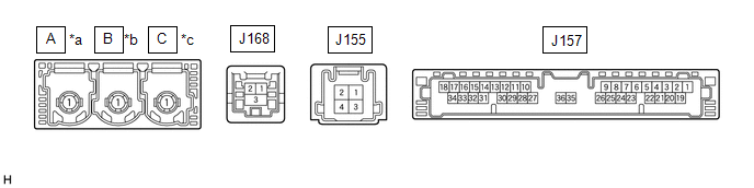
| *a | to Telephone Antenna (Sub) | *b | to GPS Antenna |
| *c | to Telephone Antenna (Main) | - | - |
| Terminal No. (Symbol) | Wiring Color | Terminal Description | Condition | Specified Condition |
|---|---|---|---|---|
| J168-1 (USB-) | - | USB communication line | - | - |
| J168-2 (USB+) | - | USB communication line | - | - |
| J168-3 (USBS) - Body ground | Shielded - Body ground | Shield ground | Always | Below 1 V |
| J157-31 (USBG) - Body ground | G - Body ground | DCM (Telematics Transceiver) power supply ground signal | Always | Below 1 V |
| J157-17 (VOT+) - J157-20 (E) | P - W-B | Sent voice signal | Vehicle occupant speaking to operator | A waveform synchronized with the voice signals received voice is output |
| J157-15 (USBV) - J157-20 (E) | L - W-B | DCM (Telematics Transceiver) power supply signal | Engine switch off | Below 1 V |
| Engine switch on (IG) | 4.5 to 5.25 V | |||
| J157-33 (VOT-) - J157-20 (E) | SB - W-B | Sent voice signal | Vehicle occupant speaking to operator | A waveform synchronized with the received voice is output |
| J157-34 (VOR-) - J157-20 (E) | LG - W-B | Receive voice signal | Operator speaking to vehicle occupant | A waveform synchronized with the sent voice is output |
| J157-18 (VOR+) - J157-20 (E) | BR - W-B | Receive voice signal | Operator speaking to vehicle occupant | A waveform synchronized with the sent voice is output |
RADIO RECEIVER ASSEMBLY
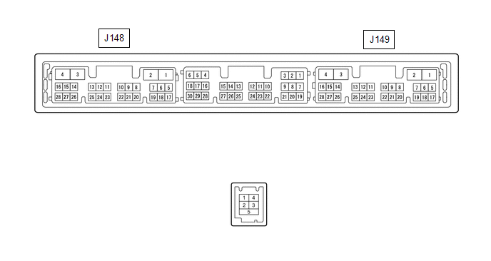
| Terminal No. (Symbol) | Wiring Color | Terminal Description | Condition | Specified Condition |
|---|---|---|---|---|
| J149-15 (VOT+) - J148-1 (GND1) | BR - W-B | Sent voice signal | Destination assist service in use and vehicle occupant speaking to operator | A waveform synchronized with the sent voice is output |
| J149-10 (USBV) - J148-1 (GND1) | L - W-B | DCM (Telematics transceiver) power supply | Engine switch on (ACC) | 4.75 to 5.25 V |
| Engine switch off | A waveform synchronized with sound is output | |||
| J149-11 (USBG) - J148-1 (GND1) | G - W-B | DCM (Telematics Transceiver) power supply ground signal | Always | Below 1 V |
| J149-12 (SGND) - Body ground | Shielded - Body ground | Shield ground | Always | Below 1 V |
| J149-13 (VOR+) - J148-1 (GND1) | P - W-B | Receive voice signal | Destination assist service in use and operator speaking to vehicle occupant | A waveform synchronized with the received voice is output |
| J149-14 (VOR-) - J148-1 (GND1) | SB - W-B | Receive voice signal | Destination assist service in use and operator speaking to vehicle occupant | A waveform synchronized with the received voice is output |
| J149-16 (VOT-) - J148-1 (GND1) | LG - W-B | Sent voice signal | Destination assist service in use and vehicle occupant speaking to operator | A waveform synchronized with the sent voice is output |
NAVIGATION ECU (w/ Navigation System)

| Terminal No. (Symbol) | Wiring Color | Terminal Description | Condition | Specified Condition |
|---|---|---|---|---|
| J164-2 (USB-) | - | USB communication line | - | - |
| J164-1 (USB+) | - | USB communication line | - | - |
| J164-3 (USBS) - Body ground | Shielded - Body ground | Shield ground | Always | Below 1 V |
 Problem Symptoms Table
PROBLEM SYMPTOMS TABLE NOTICE:
After replacing the radio receiver assembly of vehicles subscribed to pay-type satellite radio broadcasts, registration of the XM radio ID is necessary (w/ SXM Functi ...
 Confirm Cellular Phone Functionality
PROCEDURE 1. CHECK CUSTOMER'S CELLULAR PHONE COMPATIBILITY (a) Check if the cellular phone is compatible (Refer to http://www.lexus.com/MobileLink/). Result Proceed to Cellular phone ...
Other materials:
Lexus RX (RX 350L, RX450h) 2016-2026 Repair Manual > Automatic Transaxle System: Shift Solenoid "B" Circuit Short to Battery or Open (P075515)
DESCRIPTION Changing gears is performed by the ECM turning the shift solenoid valves SL1, SL2, SL3, SL4, SL5, S1 and S2 on and off. If an open or short occurs in any of the shift solenoid valve circuits, the ECM controls the remaining normal shift solenoid valves to allow the vehicle to be driven. I ...
Lexus RX (RX 350L, RX450h) 2016-2026 Repair Manual > Theft Deterrent / Keyless Entry: Id Code Box
ComponentsCOMPONENTS ILLUSTRATION *1 AIR CONDITIONER UNIT ASSEMBLY *2 ID CODE BOX (IMMOBILISER CODE ECU) InstallationINSTALLATION CAUTION / NOTICE / HINT NOTICE: Before replacing the ID code box (immobiliser code ECU), refer to Registration. Click here PROCEDURE 1. INSTALL ID CODE B ...
Lexus RX (RX 350L, RX450h) 2016-{YEAR} Owners Manual
- For your information
- Pictorial index
- For safety and security
- Instrument cluster
- Operation of each component
- Driving
- Lexus Display Audio system
- Interior features
- Maintenance and care
- When trouble arises
- Vehicle specifications
- For owners
Lexus RX (RX 350L, RX450h) 2016-{YEAR} Repair Manual

0.012