Lexus RX (RX 350L, RX450h) 2016-2026 Repair Manual: Telephone Main Antenna Circuit Short to Ground (B15CB11,B15CB13)
DESCRIPTION
This DTC is stored when the DCM (telematics transceiver) detects an open or a short in the telephone antenna (main) circuit.
| DTC No. | Detection Item | DTC Detection Condition | Trouble Area |
|---|---|---|---|
| B15CB11 | Telephone Main Antenna Circuit Short to Ground | Telephone antenna (main) impedance (Ω) is lower than the malfunction threshold for 10 seconds or more when the engine switch is on (IG) (Short circuit) |
|
| B15CB13 | Telephone Main Antenna Circuit Open | Telephone antenna (main) impedance (Ω) is higher than the malfunction threshold for 10 seconds or more when the engine switch is on (IG) (Open circuit) |
|
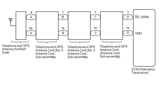
WIRING DIAGRAM
CAUTION / NOTICE / HINT
NOTICE:
Depending on the parts that are replaced during vehicle inspection or maintenance, performing initialization, registration or calibration may be needed. Refer to Precaution for Safety Connect System.
Click here .gif)
PROCEDURE
| 1. | CHECK DTC |
(a) Turn the engine switch off.
(b) Connect the Techstream to the DLC3.
(c) Turn the engine switch on (IG) and wait for 10 seconds or more.
(d) Turn the Techstream on.
(e) Clear the DTCs.
Body Electrical > Telematics > Clear DTCs(f) Check for DTCs and check that no DTCs are output.
Body Electrical > Telematics > Trouble CodesOK:
No DTCs are output.
| OK |  | USE SIMULATION METHOD TO CHECK |
|

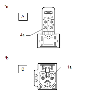
| 2. | INSPECT TELEPHONE AND GPS ANTENNA CORD (NO. 6 ANTENNA CORD SUB-ASSEMBLY) |
| (a) Disconnect the antenna connector from the Telephone and GPS antenna (for Roof Side). |
|
(b) Disconnect the antenna connector from the No. 2 antenna cord sub-assembly.
(c) Measure the resistance according to the value(s) in the table below.
Standard Resistance:
| Tester Connection | Condition | Specified Condition |
|---|---|---|
| A-4 - B-1 | Always | Below 1 Ω |
| A-4a - B-1a | Always | Below 1 Ω |
| A-4 or B-1 - Body ground | Always | 10 kΩ or higher |
| NG | | REPLACE TELEPHONE AND GPS ANTENNA CORD (NO. 6 ANTENNA CORD SUB-ASSEMBLY) |
|
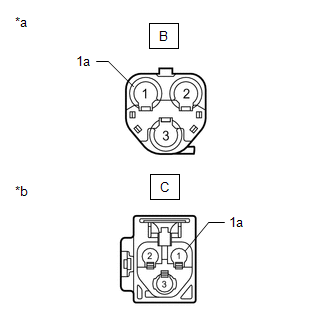
| 3. | INSPECT TELEPHONE AND GPS ANTENNA CORD (NO. 2 ANTENNA CORD SUB-ASSEMBLY) |
| (a) Disconnect the antenna connector from the No. 6 antenna cord sub-assembly. |
|
(b) Disconnect the antenna connector from the antenna cord sub-assembly.
(c) Measure the resistance according to the value(s) in the table below.
Standard Resistance:
| Tester Connection | Condition | Specified Condition |
|---|---|---|
| B-1 - C-1 | Always | Below 1 Ω |
| B-1a - C-1a | Always | Below 1 Ω |
| B-1 or C-1 - Body ground | Always | 10 kΩ or higher |
| NG | | REPLACE TELEPHONE AND GPS ANTENNA CORD (NO. 2 ANTENNA CORD SUB-ASSEMBLY) |
|
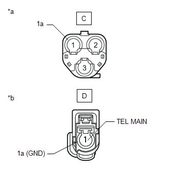
| 4. | INSPECT TELEPHONE AND GPS ANTENNA CORD (ANTENNA CORD SUB-ASSEMBLY) |
| (a) Disconnect the antenna connector from the No. 2 antenna cord sub-assembly. |
|
(b) Disconnect the antenna connector from the DCM (telematics transceiver).
(c) Measure the resistance according to the value(s) in the table below.
Standard Resistance:
| Tester Connection | Condition | Specified Condition |
|---|---|---|
| C-1 - D-1 (TEL MAIN) | Always | Below 1 Ω |
| C-1a - D-1a (GND) | Always | Below 1 Ω |
| C-1 or D-1 (TEL MAIN) - Body ground | Always | 10 kΩ or higher |
| NG | | REPLACE TELEPHONE AND GPS ANTENNA CORD (ANTENNA CORD SUB-ASSEMBLY) |
|
| 5. | CHECK TELEPHONE AND GPS ANTENNA (for Roof Side) |
(a) Replace the telephone and GPS antenna (for Roof Side) with a known good one.
Click here
(b) Clear the DTCs.
Body Electrical > Telematics > Clear DTCs(c) Recheck for DTCs and check that no DTCs are output.
Body Electrical > Telematics > Trouble CodesOK:
No DTCs are output.
| OK | | END (TELEPHONE AND GPS ANTENNA [FOR ROOF SIDE] IS DEFECTIVE) |
|
| 6. | REPLACE DCM (TELEMATICS TRANSCEIVER) |
(a) Replace the DCM (telematics transceiver) with a new one.
Click here
NOTICE:
- The engine switch must be off.
- Do not exchange the DCM (telematics transceiver) with one from another vehicle.
| NEXT | | PERFORM DCM ACTIVATION |
 Emergency Call Switch Circuit Short to Ground (B15C511,B15C513)
DESCRIPTION If the DCM (telematics transceiver) detects an error in the communication between the DCM (telematics transceiver) and the map light assembly (manual (SOS) switch) as a result of the DCM ( ...
 Backup Battery Internal Electronic Failure (B15CC49)
DESCRIPTION This DTC is set when the DCM (telematics transceiver) detects one of the following:
The mobilephone battery voltage drops or the mobilephone battery malfunctions.
The mobilephone batt ...
Other materials:
Lexus RX (RX 350L, RX450h) 2016-2026 Repair Manual > Dcm(telematics Transceiver): Installation
INSTALLATION PROCEDURE 1. INSTALL DCM (TELEMATICS TRANSCEIVER) 2. INSTALL NO. 4 TELEPHONE BRACKET (a) Install the No. 4 telephone bracket with the screw. 3. INSTALL NO. 3 TELEPHONE BRACKET (a) Install the No. 3 telephone bracket with the screw. 4. INSTALL DCM (TELEMATICS TRANSCEIVER) WITH BRACKET (a ...
Lexus RX (RX 350L, RX450h) 2016-2026 Repair Manual > Shift Lever: Disassembly
DISASSEMBLY PROCEDURE 1. REMOVE ELECTRIC PARKING BRAKE SWITCH ASSEMBLY Click here 2. REMOVE SHIFT POSITION INDICATOR (a) Remove the 2 screws, console box bracket and shift position indicator from the upper console panel sub-assembly. *1 Console Box Bracket *2 Shift Position ...
Lexus RX (RX 350L, RX450h) 2016-{YEAR} Owners Manual
- For your information
- Pictorial index
- For safety and security
- Instrument cluster
- Operation of each component
- Driving
- Lexus Display Audio system
- Interior features
- Maintenance and care
- When trouble arises
- Vehicle specifications
- For owners
Lexus RX (RX 350L, RX450h) 2016-{YEAR} Repair Manual

0.009