Lexus RX (RX 350L, RX450h) 2016-2026 Repair Manual: Emergency Call Switch Circuit Short to Ground (B15C511,B15C513)
DESCRIPTION
If the DCM (telematics transceiver) detects an error in the communication between the DCM (telematics transceiver) and the map light assembly (manual (SOS) switch) as a result of the DCM (telematics transceiver) self check, this DTC will be stored.
| DTC No. | Detection Item | DTC Detection Condition | Trouble Area |
|---|---|---|---|
| B15C511 | Emergency Call Switch Circuit Short to Ground | Manual (SOS) switch impedance (Ω) is lower than the malfunction threshold for 10 seconds or more when the engine switch is on (IG) |
|
| B15C513 | Emergency Call Switch Circuit Open | Manual (SOS) switch impedance (Ω) is higher than the malfunction threshold for 10 seconds or more when the engine switch is on (IG) |
|
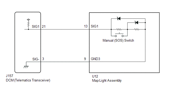
WIRING DIAGRAM
CAUTION / NOTICE / HINT
NOTICE:
Depending on the parts that are replaced during vehicle inspection or maintenance, performing initialization, registration or calibration may be needed. Refer to Precaution for Safety Connect System.
Click here .gif)
PROCEDURE
| 1. | CHECK DTC |
(a) Turn the engine switch off.
(b) Connect the Techstream to the DLC3.
(c) Turn the engine switch on (IG) and wait for 10 seconds or more.
(d) Turn the Techstream on.
(e) Clear the DTCs.
Body Electrical > Telematics > Clear DTCs(f) Check for DTCs and check that no DTCs are output.
Body Electrical > Telematics > Trouble CodesOK:
No DTCs are output.
| OK |  | USE SIMULATION METHOD TO CHECK |
|

| 2. | INSPECT MAP LIGHT ASSEMBLY (MANUAL (SOS) SWITCH) |
| (a) Remove the map light assembly (manual (SOS) switch). Click here |
|
(b) Measure the resistance according to the value(s) in the table below.
Standard Resistance:
| Tester Connection | Condition | Specified Condition |
|---|---|---|
| 13 (SIG1) - 14 (GND3) | Manual (SOS) switch not operated | 410 to 414 Ω |
| 13 (SIG1) - 14 (GND3) | Manual (SOS) switch operated | 81 to 83 Ω |
| NG | | REPLACE MAP LIGHT ASSEMBLY (MANUAL (SOS) SWITCH) |
|
| 3. | CHECK HARNESS AND CONNECTOR (DCM (TELEMATICS TRANSCEIVER) - MAP LIGHT ASSEMBLY (MANUAL (SOS) SWITCH)) |
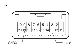
(a) Disconnect the J157 DCM (telematics transceiver) connector.
(b) Disconnect the U12 map light assembly (manual (SOS) switch) connector.
(c) Measure the resistance according to the value(s) in the table below.
Standard Resistance:
| Tester Connection | Condition | Specified Condition |
|---|---|---|
| J157-21 (SIG1) - U12-13 (SIG1) | Always | Below 1 Ω |
| J157-3 (SIG-) - U12-9 (GND3) | Always | Below 1 Ω |
| J157-21 (SIG1) or U12-13 (SIG1) - Body ground | Always | 10 kΩ or higher |
| J157-3 (SIG-) or U12-9 (GND3) - Body ground | Always | 10 kΩ or higher |
| NG | | REPAIR OR REPLACE HARNESS OR CONNECTOR |
|
| 4. | REPLACE DCM (TELEMATICS TRANSCEIVER) |
(a) Replace the DCM (telematics transceiver) with a new one.
Click here
NOTICE:
- The engine switch must be off.
- Do not exchange the DCM (telematics transceiver) with one from another vehicle.
| NEXT | | PERFORM DCM ACTIVATION |
 Airbag Signal Signal Plausibility Failure (B15C464)
DESCRIPTION If the DCM (telematics transceiver) detects an error in communication between the DCM (telematics transceiver) and the airbag sensor assembly as a result of the DCM (telematics transceiver ...
 Telephone Main Antenna Circuit Short to Ground (B15CB11,B15CB13)
DESCRIPTION This DTC is stored when the DCM (telematics transceiver) detects an open or a short in the telephone antenna (main) circuit. DTC No. Detection Item DTC Detection Condition Trouble ...
Other materials:
Lexus RX (RX 350L, RX450h) 2016-2026 Repair Manual > Seat Heater System: Front Left Seat Heat Sensor Circuit (B14C1)
DESCRIPTION Output to the front seat cushion heater temperature sensor stops if one of the following occurs: 1) the temperature sensor is open or shorted; or 2) the temperature sensor is damaged and its output value does not change. DTC No. Detection Item DTC Detection Condition Trouble Are ...
Lexus RX (RX 350L, RX450h) 2016-2026 Repair Manual > Audio And Visual System (for 12.3 Inch Display): Operation Check
OPERATION CHECK REMOTE TOUCH (REMOTE OPERATION CONTROLLER ASSEMBLY) SELF CHECK NOTICE:
Before entering self-diagnostic mode, make sure there are no obstructions which may interfere with operation of the remote touch screen, and that the remote touch screen is not dirty.
Do not touch the remote ...
Lexus RX (RX 350L, RX450h) 2016-{YEAR} Owners Manual
- For your information
- Pictorial index
- For safety and security
- Instrument cluster
- Operation of each component
- Driving
- Lexus Display Audio system
- Interior features
- Maintenance and care
- When trouble arises
- Vehicle specifications
- For owners
Lexus RX (RX 350L, RX450h) 2016-{YEAR} Repair Manual

0.0109