Lexus RX (RX 350L, RX450h) 2016-2026 Repair Manual: Airbag Signal Signal Plausibility Failure (B15C464)
DESCRIPTION
If the DCM (telematics transceiver) detects an error in communication between the DCM (telematics transceiver) and the airbag sensor assembly as a result of the DCM (telematics transceiver) self check, this DTC will be set.
| DTC No. | Detection Item | DTC Detection Condition | Trouble Area |
|---|---|---|---|
| B15C464 | Airbag Signal Signal Plausibility Failure | DCM (telematics transceiver) detects an error in signals from airbag sensor assembly when engine switch is on (IG). |
|
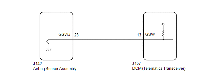
WIRING DIAGRAM
CAUTION / NOTICE / HINT
NOTICE:
-
The vehicle is equipped with an SRS (Supplemental Restraint System) which includes components such as airbags. Before servicing (including removal or installation of parts), be sure to read the Precaution in the SRS.
Click here
.gif)
-
After turning the engine switch off, waiting time may be required before disconnecting the cable from the negative (-) battery terminal. Therefore, make sure to read the disconnecting the cable from the negative (-) battery terminal notices before proceeding with work.
Click here
PROCEDURE
| 1. | CHECK DTC (AIRBAG SYSTEM) |
(a) Turn the engine switch off.
(b) Connect the Techstream to the DLC3.
(c) Turn the engine switch on (IG) and wait for 10 seconds or more.
(d) Turn the Techstream on.
(e) Clear the DTCs.
Body Electrical > SRS Airbag > Clear DTCs(f) Check for DTCs and check that no DTCs are output.
Body Electrical > SRS Airbag > Trouble CodesOK:
No DTCs are output.
| NG | .gif) | GO TO AIRBAG SYSTEM |
|
.gif)
| 2. | CHECK DTC |
(a) Turn the engine switch off.
(b) Connect the Techstream to the DLC3.
(c) Turn the engine switch on (IG) and wait for 10 seconds or more.
(d) Turn the Techstream on.
(e) Clear the DTCs.
Body Electrical > Telematics > Clear DTCs(f) Check for DTCs and check that no DTCs are output.
Body Electrical > Telematics > Trouble CodesOK:
No DTCs are output.
| OK | | USE SIMULATION METHOD TO CHECK |
|
| 3. | CHECK DCM (TELEMATICS TRANSCEIVER) (GSW SIGNAL) |
| (a) Remove the DCM (telematics transceiver) but do not disconnect the connectors. Click here |
|
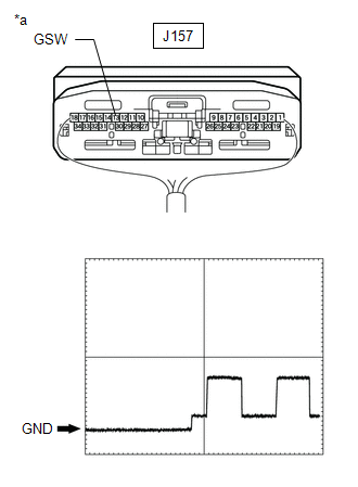
(b) Check the input waveform.
(1) Check the signal waveform according to the condition(s) in the table below. (Check the waveform from the back of the wire harness connector of the DCM (telematics transceiver) while the airbag sensor assembly connectors are connected.)
Reference Waveform:
| Item | Condition |
|---|---|
| Tester connection | J157-13 (GSW) - Body ground |
| Tool setting | 5.0 V/DIV., 20 ms/DIV. |
| Vehicle condition | Engine switch on (IG) |
OK:
The waveform is similar to that shown in the illustration.
| NG | | GO TO STEP 5 |
|
| 4. | REPLACE DCM (TELEMATICS TRANSCEIVER) |
(a) Replace the DCM (telematics transceiver).
Click here
NOTICE:
- The engine switch must be off.
- Do not exchange the DCM (telematics transceiver) with one from another vehicle.
| NEXT | | PERFORM DCM ACTIVATION |
| 5. | CHECK HARNESS AND CONNECTOR (DCM [TELEMATICS TRANSCEIVER] - AIRBAG SENSOR ASSEMBLY) |
(a) Disconnect the J157 DCM (telematics transceiver) connector.
(b) Disconnect the J142 airbag sensor assembly connector.
(c) Measure the resistance according to the value(s) in the table below.
Standard Resistance:
| Tester Connection | Condition | Specified Condition |
|---|---|---|
| J157-13 (GSW) - J142-22 (GSW3) | Always | Below 1 Ω |
| J157-13 (GSW) - Body ground | Always | 10 kΩ or higher |
| OK | | REPLACE AIRBAG SENSOR ASSEMBLY |
| NG | | REPAIR OR REPLACE HARNESS OR CONNECTOR |
 GNSS Antenna Circuit Short to Ground (B15C111,B15C113)
DESCRIPTION These DTCs are stored when a malfunction occurs in the telephone and GPS antenna (for Roof Side) circuit. DTC No. Detection Item DTC Detection Condition Trouble Area B15C111 ...
 Emergency Call Switch Circuit Short to Ground (B15C511,B15C513)
DESCRIPTION If the DCM (telematics transceiver) detects an error in the communication between the DCM (telematics transceiver) and the map light assembly (manual (SOS) switch) as a result of the DCM ( ...
Other materials:
Lexus RX (RX 350L, RX450h) 2016-2026 Repair Manual > Immobiliser System: Antenna Coil Open / Short (B2784)
DESCRIPTION When an open or short circuit is detected in the transponder key amplifier coil built into the engine switch, the certification ECU (smart key ECU assembly) stores this DTC. This DTC is also stored as a history DTC. DTC No. Detection Item DTC Detection Condition Trouble Area N ...
Lexus RX (RX 350L, RX450h) 2016-2026 Repair Manual > Automatic Transaxle System: Pressure Control Solenoid "G" Circuit Open (P280713)
DESCRIPTION Changing gears is performed by the ECM turning the shift solenoid valves SL1, SL2, SL3, SL4 and SL5 on and off. If an open or short occurs in any of the shift solenoid valve circuits, the ECM controls the remaining normal shift solenoid valves to allow the vehicle to be driven. If all of ...
Lexus RX (RX 350L, RX450h) 2016-{YEAR} Owners Manual
- For your information
- Pictorial index
- For safety and security
- Instrument cluster
- Operation of each component
- Driving
- Lexus Display Audio system
- Interior features
- Maintenance and care
- When trouble arises
- Vehicle specifications
- For owners
Lexus RX (RX 350L, RX450h) 2016-{YEAR} Repair Manual

0.0104