Lexus RX (RX 350L, RX450h) 2016-2026 Repair Manual: GNSS Antenna Circuit Short to Ground (B15C111,B15C113)
DESCRIPTION
These DTCs are stored when a malfunction occurs in the telephone and GPS antenna (for Roof Side) circuit.
| DTC No. | Detection Item | DTC Detection Condition | Trouble Area |
|---|---|---|---|
| B15C111 | GNSS Antenna Circuit Short to Ground | Current to the GNSS antenna is lower than the malfunction threshold for 10 seconds or more when the engine switch is on (IG) (Short circuit) |
|
| B15C113 | GNSS Antenna Circuit Open | Current to the GNSS antenna is higher than the malfunction threshold for 10 seconds or more when the engine switch is on (IG) (Open circuit) |
|
WIRING DIAGRAM

CAUTION / NOTICE / HINT
NOTICE:
Depending on the parts that are replaced during vehicle inspection or maintenance, performing initialization, registration or calibration may be needed. Refer to Precaution for Safety Connect System.
Click here .gif)
PROCEDURE
| 1. | CHECK DTC |
(a) Turn the engine switch off.
(b) Connect the Techstream to the DLC3.
(c) Turn the engine switch on (IG) and wait for 10 seconds or more.
(d) Turn the Techstream on.
(e) Clear the DTCs.
Body Electrical > Telematics > Clear DTCs(f) Check for DTCs and check that no DTCs are output.
Body Electrical > Telematics > Trouble CodesOK:
No DTCs are output.
| OK | .gif) | USE SIMULATION METHOD TO CHECK |
|

| 2. | INSPECT TELEPHONE AND GPS ANTENNA CORD (NO. 6 ANTENNA CORD SUB-ASSEMBLY) |
| (a) Disconnect the antenna connector from the Telephone and GPS antenna (for Roof Side). |
|

(b) Disconnect the antenna connector from the No. 2 antenna cord sub-assembly.
(c) Measure the resistance according to the value(s) in the table below.
Standard Resistance:
| Tester Connection | Condition | Specified Condition |
|---|---|---|
| A-5 - B-2 | Always | Below 1 Ω |
| A-5a - B-2a | Always | Below 1 Ω |
| A-5 or B-2 - Body ground | Always | 10 kΩ or higher |
| NG | | REPLACE TELEPHONE AND GPS ANTENNA CORD (NO. 6 ANTENNA CORD SUB-ASSEMBLY) |
|
| 3. | INSPECT TELEPHONE AND GPS ANTENNA CORD (NO. 2 ANTENNA CORD SUB-ASSEMBLY) |
| (a) Disconnect the antenna connector from the No. 6 antenna cord sub-assembly. |
|

(b) Disconnect the antenna connector from the antenna cord sub-assembly.
(c) Measure the resistance according to the value(s) in the table below.
Standard Resistance:
| Tester Connection | Condition | Specified Condition |
|---|---|---|
| B-2 - C-2 | Always | Below 1 Ω |
| B-2a - C-2a | Always | Below 1 Ω |
| B-2 or C-2 - Body ground | Always | 10 kΩ or higher |
| NG | | REPLACE TELEPHONE AND GPS ANTENNA CORD (NO. 2 ANTENNA CORD SUB-ASSEMBLY) |
|
| 4. | INSPECT TELEPHONE AND GPS ANTENNA CORD (ANTENNA CORD SUB-ASSEMBLY) |
| (a) Disconnect the antenna connector from the No. 2 antenna cord sub-assembly. |
|
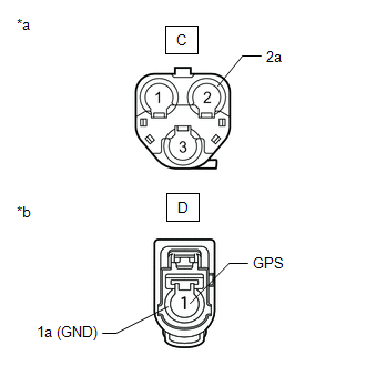
(b) Disconnect the antenna connector from the DCM (telematics transceiver).
(c) Measure the resistance according to the value(s) in the table below.
Standard Resistance:
| Tester Connection | Condition | Specified Condition |
|---|---|---|
| C-2 - D-1 (GPS) | Always | Below 1 Ω |
| C-2a - D-1a (GND) | Always | Below 1 Ω |
| C-2 or D-1 (GND) - Body ground | Always | 10 kΩ or higher |
| NG | | REPLACE TELEPHONE AND GPS ANTENNA CORD (ANTENNA CORD SUB-ASSEMBLY) |
|
| 5. | CHECK TELEPHONE AND GPS ANTENNA (FOR ROOF SIDE) |
(a) Replace the telephone and GPS antenna (for Roof Side) with a known good one.
Click here
(b) Clear the DTCs.
Body Electrical > Telematics > Clear DTCs(c) Recheck for DTCs and check that no DTCs are output.
Body Electrical > Telematics > Trouble CodesOK:
No DTCs are output.
| OK | | END (TELEPHONE AND GPS ANTENNA [FOR ROOF SIDE] IS DEFECTIVE) |
|
| 6. | REPLACE DCM (TELEMATICS TRANSCEIVER) |
(a) Replace the DCM (telematics transceiver) with a new one.
Click here
NOTICE:
- The engine switch must be off.
- Do not exchange the DCM (telematics transceiver) with one from another vehicle.
| NEXT | | PERFORM DCM ACTIVATION |
 DCM System Internal Failure (B15A804)
DESCRIPTION This DTC is stored when an internal circuit malfunction is detected by the DCM (telematics transceiver) self check. DTC No. Detection Item DTC Detection Condition Trouble Area ...
 Airbag Signal Signal Plausibility Failure (B15C464)
DESCRIPTION If the DCM (telematics transceiver) detects an error in communication between the DCM (telematics transceiver) and the airbag sensor assembly as a result of the DCM (telematics transceiver ...
Other materials:
Lexus RX (RX 350L, RX450h) 2016-2026 Repair Manual > Power Tilt And Power Telescopic Steering Column System: How To Proceed With Troubleshooting
CAUTION / NOTICE / HINT HINT: *: Use the Techstream. PROCEDURE 1. VEHICLE BROUGHT TO WORKSHOP
NEXT 2. INSPECT BATTERY VOLTAGE Standard voltage: 11 to 14 V If the voltage is below 11 V, recharge or replace the battery before proceeding.
NEXT 3. ...
Lexus RX (RX 350L, RX450h) 2016-2026 Repair Manual > Wiper And Washer System: Problem Symptoms Table
PROBLEM SYMPTOMS TABLE HINT: Use the table below to help determine the cause of problem symptoms. If multiple suspected areas are listed, the potential causes of the symptoms are listed in order of probability in the "Suspected Area" column of the table. Check each symptom by checking the suspected ...
Lexus RX (RX 350L, RX450h) 2016-{YEAR} Owners Manual
- For your information
- Pictorial index
- For safety and security
- Instrument cluster
- Operation of each component
- Driving
- Lexus Display Audio system
- Interior features
- Maintenance and care
- When trouble arises
- Vehicle specifications
- For owners
Lexus RX (RX 350L, RX450h) 2016-{YEAR} Repair Manual

0.0121