Lexus RX (RX 350L, RX450h) 2016-2026 Repair Manual: GVIF Disconnected (from EMV/MM Integrated Device to Multi Display) (B1575)
DESCRIPTION
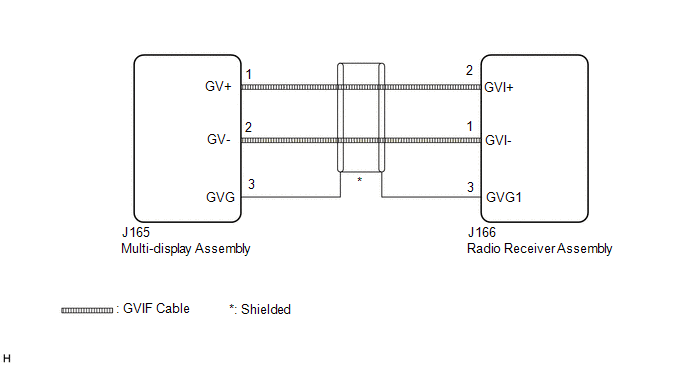
The radio receiver assembly and multi-display assembly are connected via video signal (digital) lines.
This DTC is stored when a video signal (digital) line is disconnected.
| DTC No. | Detection Item | DTC Detection Condition | Trouble Area |
|---|---|---|---|
| B1575 | GVIF Disconnected (from EMV/MM Integrated Device to Multi Display) | GVIF disconnected (from radio receiver assembly to multi-display assembly) |
|
WIRING DIAGRAM
CAUTION / NOTICE / HINT
NOTICE:
Depending on the parts that are replaced during vehicle inspection or maintenance, performing initialization, registration or calibration may be needed. Refer to Precaution for Navigation System.
Click here .gif)
PROCEDURE
| 1. | CHECK DTC |
(a) Clear the DTCs.
Body Electrical > Navigation System > Clear DTCs(b) Turn the engine switch off.
(c) Recheck for DTCs and check that no DTCs are output.
Body Electrical > Navigation System > Trouble CodesOK:
No DTCs are output.
| OK |  | USE SIMULATION METHOD TO CHECK |
|

| 2. | CHECK HARNESS AND CONNECTOR (MULTI-DISPLAY ASSEMBLY - RADIO RECEIVER ASSEMBLY) |
| (a) Disconnect the J165 multi-display assembly connector. |
|
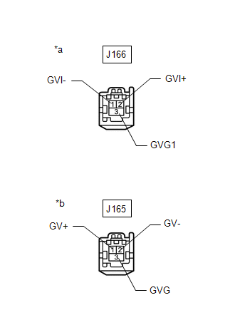
(b) Disconnect the J166 radio receiver assembly connector.
(c) Measure the resistance according to the value(s) in the table below.
Standard Resistance:
| Tester Connection | Condition | Specified Condition |
|---|---|---|
| J166-2 (GVI+) - J165-1 (GV+) | Always | Below 1 Ω |
| J166-1 (GVI-) - J165-2 (GV-) | Always | Below 1 Ω |
| J166-3 (GVG1) - J165-3 (GVG) | Always | Below 1 Ω |
| J166-2 (GVI+) or J165-1 (GV+) - Body ground | Always | 10 kΩ or higher |
| J166-1 (GVI-) or J165-2 (GV-) - Body ground | Always | 10 kΩ or higher |
| J166-3 (GVG1) or J165-3 (GVG) - Body ground | Always | 10 kΩ or higher |
| NG | | REPAIR OR REPLACE HARNESS OR CONNECTOR |
|
| 3. | CHECK MULTI-DISPLAY ASSEMBLY |
(a) Replace the multi-display assembly with a new or known good one.
Click here
(b) Clear the DTCs.
Body Electrical > Navigation System > Clear DTCs(c) Turn the engine switch off.
(d) Recheck for DTCs and check that no DTCs are output.
Body Electrical > Navigation System > Trouble CodesOK:
No DTCs are output.
| OK | | END (MULTI-DISPLAY ASSEMBLY IS DEFECTIVE) |
| NG | | REPLACE RADIO RECEIVER ASSEMBLY |
 GVIF Disconnected (from Park Assist/Monitoring ECU to EMV/MM Integrated Device) (B1574)
DESCRIPTION The multi-display assembly and parking assist ECU are connected via video signal (digital) lines. This DTC is stored when a video signal (digital) line is disconnected. DTC No. Detect ...
 Voice Recognition Microphone Disconnected (B1579)
DESCRIPTION The radio receiver assembly and telephone microphone assembly are connected to each other using the microphone connection detection signal lines. This DTC is stored when a microphone conne ...
Other materials:
Lexus RX (RX 350L, RX450h) 2016-2026 Repair Manual > Blind Spot Monitor System: Precaution
PRECAUTION PRECAUTION FOR DISCONNECTING CABLE FROM NEGATIVE BATTERY TERMINAL NOTICE: When disconnecting the cable from the negative (-) battery terminal, initialize the following systems after the cable is reconnected. System Name See Procedure LKA/LDA System Intelligent Clearance ...
Lexus RX (RX 350L, RX450h) 2016-2026 Repair Manual > Roof Antenna: Removal
REMOVAL CAUTION / NOTICE / HINT The necessary procedures (adjustment, calibration, initialization, or registration) that must be performed after parts are removed and installed, or replaced during telephone antenna assembly removal/installation are shown below. Necessary Procedures After Parts Remov ...
Lexus RX (RX 350L, RX450h) 2016-{YEAR} Owners Manual
- For your information
- Pictorial index
- For safety and security
- Instrument cluster
- Operation of each component
- Driving
- Lexus Display Audio system
- Interior features
- Maintenance and care
- When trouble arises
- Vehicle specifications
- For owners
Lexus RX (RX 350L, RX450h) 2016-{YEAR} Repair Manual

0.015