Lexus RX (RX 350L, RX450h) 2016-2026 Repair Manual: Switch Lights of Remote Touch do not Illuminate
DESCRIPTION
Power is supplied to the remote touch (remote operation controller assembly) illumination when the light control switch is in the tail or head position.
WIRING DIAGRAM

CAUTION / NOTICE / HINT
NOTICE:
Inspect the fuse for circuits related to this system before performing the following procedure.
PROCEDURE
| 1. | CHECK SYMPTOMS |
| (a) Perform the following procedure and check the switch illumination again. (1) If the vehicle is in a bright area, move it to a dark area. HINT: When the vehicle is in a bright area, the switch illumination may not turn on due to the automatic dimmer function. (2) Set the rheostat to maximum brightness. HINT: If the brightness of the rheostat is set to low, switch illumination may not be recognized even when the switch illumination turns on. (3) If the light control switch is in the AUTO position, turn the switch to the tail or head position. HINT: If the light control switch is in the AUTO position, the switch illumination will not turn on unless the surrounding area is dark. OK: Switch illumination turns on. |
|

| OK | .gif) | END |
|
.gif)
| 2. | REMOTE TOUCH (REMOTE OPERATION CONTROLLER ASSEMBLY) SELF CHECK (SWITCH ILLUMINATION CHECK) |
(a) Enter self-diagnostic mode.
Click here .gif)
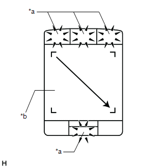
| (b) Operate the remote touch screen diagonally from the upper left to the lower right and check that the brightness of the switch illumination changes. NOTICE: Since the remote touch screen may recognize a pinch in/out or flick operation if operated with 2 fingers, always use 1 finger to operate the remote touch screen in self-diagnostic mode. OK: Brightness changes according to remote touch screen operation. |
|
| NG | | REPLACE REMOTE TOUCH (REMOTE OPERATION CONTROLLER ASSEMBLY) |
|
| 3. | CHECK HARNESS AND CONNECTOR (ILLUMINATION SIGNAL CIRCUIT) |
(a) Disconnect the J154 remote touch (remote operation controller assembly) connector.
(b) Measure the voltage according to the value(s) in the table below.
Standard Voltage:
| Tester Connection | Condition | Specified Condition |
|---|---|---|
| J154-2 (ILL+) - Body ground | Light control switch in tail or head position | 11 to 14 V |
| NG | | REPAIR OR REPLACE HARNESS OR CONNECTOR |
|
| 4. | CHECK HARNESS AND CONNECTOR (REMOTE TOUCH (REMOTE OPERATION CONTROLLER ASSEMBLY) - COMBINATION METER ASSEMBLY) |
(a) Disconnect the J154 remote touch (remote operation controller assembly) connector.
(b) Disconnect the J10 combination meter assembly connector.
(c) Measure the resistance according to the value(s) in the table below.
Standard Resistance:
| Tester Connection | Condition | Specified Condition |
|---|---|---|
| J154-5 (ILL-) - J10-39 (ILL-) | Always | Below 1 Ω |
| J154-5 (ILL-) or J10-39 (ILL-) - Body ground | Always | 10 kΩ or higher |
| NG | | REPAIR OR REPLACE HARNESS OR CONNECTOR |
|
| 5. | REPLACE REMOTE TOUCH (REMOTE OPERATION CONTROLLER ASSEMBLY) |
(a) Replace the remote touch (remote operation controller assembly) with a new or known good one.
Click here
(b) Check if the switch illumination turns on.
OK:
The switch illumination turns on when the light control switch is in the tail or head position.
| OK | | END |
| NG | | GO TO METER / GAUGE SYSTEM |
 Switch Lights of Remote Touch Always Illuminate or cannot be Controlled Using Rheostat
DESCRIPTION Power is supplied to the remote touch (remote operation controller assembly) illumination when the light control switch is in the tail or head position. HINT:
When the remote touch (rem ...
 Switch Operation of Remote Touch not Accepted
CAUTION / NOTICE / HINT NOTICE: Depending on the parts that are replaced during vehicle inspection or maintenance, performing initialization, registration or calibration may be needed. Refer to Precau ...
Other materials:
Lexus RX (RX 350L, RX450h) 2016-2026 Repair Manual > Water Pump: Components
COMPONENTS ILLUSTRATION *1 ENGINE WATER PUMP ASSEMBLY *2 NO. 2 IDLER PULLEY SUB-ASSEMBLY *3 WATER PUMP PULLEY *4 WATER PUMP GASKET *5 V-RIBBED BELT - - N*m (kgf*cm, ft.*lbf): Specified torque ● Non-reusable part Adhesive 1344 ★ Precoated part ...
Lexus RX (RX 350L, RX450h) 2016-2026 Repair Manual > Occupant Classification System: Fail-safe Chart
FAIL-SAFE CHART FAIL-SAFE FUNCTION (a) The following chart shows the status of the front passenger SRS items and passenger airbag ON/OFF indicator operation under each condition.
The passenger airbag ON/OFF indicator ("ON" and "OFF") comes on for approximately 4 seconds, then goes off for approxi ...
Lexus RX (RX 350L, RX450h) 2016-{YEAR} Owners Manual
- For your information
- Pictorial index
- For safety and security
- Instrument cluster
- Operation of each component
- Driving
- Lexus Display Audio system
- Interior features
- Maintenance and care
- When trouble arises
- Vehicle specifications
- For owners
Lexus RX (RX 350L, RX450h) 2016-{YEAR} Repair Manual

0.0129