Lexus RX (RX 350L, RX450h) 2016-2026 Repair Manual: Pointer Displayed/not Displayed Repeatedly
WIRING DIAGRAM
CAUTION / NOTICE / HINT
NOTICE:
-
Depending on the parts that are replaced during vehicle inspection or maintenance, performing initialization, registration or calibration may be needed. Refer to Precaution for Navigation System.
Click here
.gif)
- Inspect the fuses for circuits related to this system before performing the following procedure.
PROCEDURE
| 1. | CHECK SYMPTOMS |
(a) Recheck the situation when the malfunction occurs.
HINT:
- When a hand is rested on the remote touch screen while driving, the remote touch (remote operation controller assembly) may react to finger movements and repeatedly display and hide the pointer.
- When accelerating excessively on rough roads, the remote touch (remote operation controller assembly) may react to the acceleration and repeatedly display and hide the pointer.
| Result | Proceed to |
|---|---|
| Symptom occurs in any situation. | A |
| Symptom occurs when hand is rested on the remote touch screen while driving. | B |
| Symptom occurs when accelerating excessively on rough roads. | C |
| B | .gif) | END |
| C | | GO TO STEP 5 |
|
.gif)
| 2. | CHECK FOR FOREIGN MATTER |
(a) Check if there is any foreign matter around the remote touch screen that interferes with operation of the screen.
OK:
There is no foreign matter around the remote touch screen that interferes with operation of the screen.
| NG | | REMOVE FOREIGN MATTER (CHECK OPERATION AGAIN) |
|
| 3. | REMOTE TOUCH (REMOTE OPERATION CONTROLLER ASSEMBLY) SELF CHECK (CHECK REMOTE TOUCH SCREEN OPERATION POSITION RECOGNITION CONDITION) |
(a) Enter self-diagnostic mode.
Click here
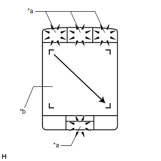
| (b) Operate the remote touch screen diagonally from the upper left to the lower right and check that the brightness of the switch illumination changes. NOTICE: Since the remote touch screen may recognize a pinch in/out operation if operated with 2 fingers, always use 1 finger to operate the remote touch screen in self-diagnostic mode. OK: Brightness changes according to remote touch screen operation.
HINT: When the switch illumination blinks, the remote touch (remote operation controller assembly) has stored a DTC. |
|
| B | | REPLACE REMOTE TOUCH (REMOTE OPERATION CONTROLLER ASSEMBLY) |
|
| 4. | REPLACE NAVIGATION ECU |
(a) Replace the navigation ECU with a new or known good one.
Click here
(b) Check the malfunction disappears.
OK:
Malfunction disappears.
| OK | | END (NAVIGATION ECU IS DEFECTIVE) |
| NG | | REPLACE RADIO RECEIVER ASSEMBLY |
| 5. | CHECK CONNECTOR CONNECTION CONDITION |
(a) Check if the J154 remote touch (remote operation controller assembly) connector is securely connected.
OK:
The connector is securely connected.
| NG | | SECURELY CONNECTED |
|
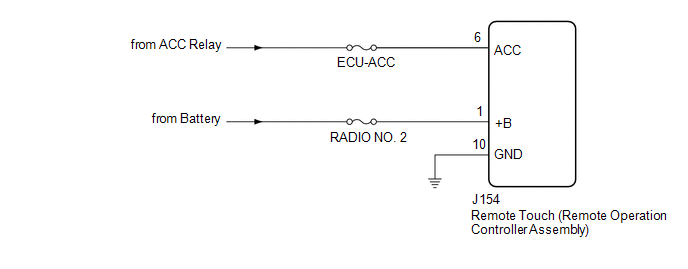
| 6. | CHECK HARNESS AND CONNECTOR (REMOTE TOUCH (REMOTE OPERATION CONTROLLER ASSEMBLY) POWER SOURCE) |
(a) Disconnect the J154 remote touch (remote operation controller assembly) connector.
(b) Measure the resistance according to the value(s) in the table below.
Standard Resistance:
| Tester Connection | Condition | Specified Condition |
|---|---|---|
| J154-10 (GND) - Body ground | Always | Below 1 Ω |
(c) Measure the voltage according to the value(s) in the table below.
Standard Voltage:
| Tester Connection | Condition | Specified Condition |
|---|---|---|
| J154-1 (+B) - Body ground | Always | 11 to 14 V |
| J154-6 (ACC) - Body ground | Engine switch on (ACC) | 11 to 14 V |
| OK | | REPLACE REMOTE TOUCH (REMOTE OPERATION CONTROLLER ASSEMBLY) |
| NG | | REPAIR OR REPLACE HARNESS OR CONNECTOR |
 Switch Operation of Remote Touch not Accepted
CAUTION / NOTICE / HINT NOTICE: Depending on the parts that are replaced during vehicle inspection or maintenance, performing initialization, registration or calibration may be needed. Refer to Precau ...
 Pointer not Displayed on Screen or Pointer does not Move
CAUTION / NOTICE / HINT NOTICE: Depending on the parts that are replaced during vehicle inspection or maintenance, performing initialization, registration or calibration may be needed. Refer to Precau ...
Other materials:
Lexus RX (RX 350L, RX450h) 2016-2026 Repair Manual > Steering Gear: Inspection
INSPECTION PROCEDURE 1. INSPECT TIE ROD ASSEMBLY LH (a) Secure the tie rod assembly LH in a vise between aluminum plates. NOTICE: Do not overtighten the vise. (b) Install the nut to the stud bolt. (c) Flip the ball joint back and forth 5 times. (d) Using a torque wrench and the nut, t ...
Lexus RX (RX 350L, RX450h) 2016-2026 Repair Manual > Theft Deterrent System: Theft Warning Siren Circuit
DESCRIPTION The theft warning siren assembly sounds if either of the following conditions is met:
The theft deterrent system is in the alarm sounding state.
The theft warning siren assembly is in the armed state when the power source, ground or communication line is open.
WIRING DIAGRAM CAU ...
Lexus RX (RX 350L, RX450h) 2016-{YEAR} Owners Manual
- For your information
- Pictorial index
- For safety and security
- Instrument cluster
- Operation of each component
- Driving
- Lexus Display Audio system
- Interior features
- Maintenance and care
- When trouble arises
- Vehicle specifications
- For owners
Lexus RX (RX 350L, RX450h) 2016-{YEAR} Repair Manual

0.011