Lexus RX (RX 350L, RX450h) 2016-2026 Repair Manual: Removal
REMOVAL
CAUTION / NOTICE / HINT
The necessary procedures (adjustment, calibration, initialization or registration) that must be performed after parts are removed and installed, or replaced during transmission valve body assembly removal/installation are shown below.
Necessary Procedures After Parts Removed/Installed/Replaced| Replacement Part or Performed Procedure | Necessary Procedure | Effect/Inoperative Function when Necessary Procedure not Performed | Link |
|---|---|---|---|
|
*1: When performing learning using the Techstream.
Click here | |||
| Battery terminal is disconnected/reconnected | Memorize steering angle neutral point | Lane Control System | |
| Pre-collision System | |||
| Intelligent Clearance Sonar System*1 | |||
| Lighting System (w/ Automatic Headlight Beam Level Control System) | | ||
| Parking Assist Monitor System | | ||
| Panoramic View Monitor System | | ||
| Initialize back door lock | Power Door Lock Control System | | |
| Reset back door close position | Power Back Door System (w/ Outside Door Control Switch) | | |
| Front wheel alignment adjustment |
|
| |
| Suspension, tires, etc. (The vehicle height changes because of suspension or tire replacement) |
|
| |
| Rear television camera assembly optical axis (Back camera position setting) | Parking Assist Monitor System | | |
| Panoramic View Monitor System | | |
| Initialize No. 1 headlight ECU sub-assembly LH | Lighting System (w/ Automatic Headlight Beam Level Control System) | | |
| Gas leak from exhaust system is repaired | Inspection After Repair |
| |
| Replacement of
| Perform the following procedures in the order shown:
|
| |
| Replacement of shift solenoid valve SL1 and/or SL2 | Perform Road Test to Allow ECM to Learn | ||
PROCEDURE
1. REMOVE FRONT WHEEL LH
Click here .gif)
2. REMOVE FRONT WHEEL OPENING EXTENSION PAD LH
Click here
3. REMOVE NO. 3 ENGINE UNDER COVER
Click here
4. REMOVE FRONT FENDER APRON SEAL LH
Click here
5. DRAIN AUTOMATIC TRANSAXLE FLUID
Click here
6. REMOVE FRONT FRAME ASSEMBLY
Click here
7. REMOVE FRONT ENGINE MOUNTING INSULATOR
Click here
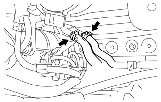
8. DISCONNECT NO. 1 TRANSMISSION OIL COOLER HOSE ASSEMBLY
| (a) Slide the 2 clips and disconnect the 2 No. 1 transmission oil cooler hose assemblies. |
|
9. REMOVE OUTLET NO. 1 OIL COOLER TUBE SUB-ASSEMBLY
| (a) Remove the 2 bolts and outlet No. 1 oil cooler tube sub-assembly from the transaxle housing. |
|
.png)
| (b) Remove the O-ring from the outlet No. 1 oil cooler tube sub-assembly. |
|
.png)
10. REMOVE INLET NO. 1 OIL COOLER TUBE SUB-ASSEMBLY
| (a) Remove the 2 bolts and inlet No. 1 oil cooler tube sub-assembly from the transaxle housing. |
|
.png)
| (b) Remove the O-ring from the inlet No. 1 oil cooler tube sub-assembly. |
|
.png)
11. REMOVE TRANSAXLE SIDE COVER SUB-ASSEMBLY
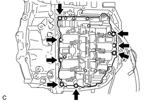
| (a) Using a T40 "TORX" socket wrench, remove the 13 bolts. |
|
.png)
| (b) Insert the blade of an oil pan seal cutter between the transaxle side cover sub-assembly and automatic transaxle case sub-assembly, cut through the applied seal packing and remove the transaxle side cover sub-assembly. NOTICE: Be careful not to damage the sealing surface of the automatic transaxle case sub-assembly. |
|
.png)
12. REMOVE TRANSMISSION VALVE BODY ASSEMBLY
| (a) Disconnect the transmission revolution sensor (NT) connector and transmission revolution sensor (NC) connector. |
|
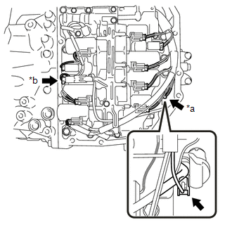
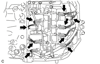
| (b) Disconnect the 9 shift solenoid valve connectors. |
|
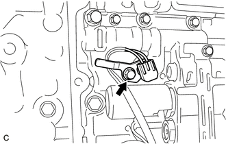
| (c) Remove the bolt and temperature sensor clamp, and disconnect the temperature sensor from the transmission valve body assembly. |
|
| (d) Disengage the clamp and guide to disconnect the transmission revolution sensor (NC) wire. |
|

| (e) Remove the 8 bolts. |
|
| (f) Separate the manual valve connecting rod from the manual valve lever sub-assembly. |
|
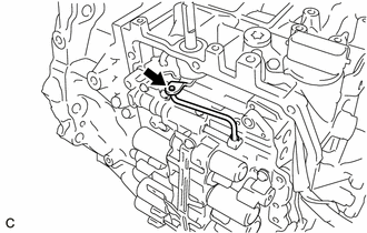
(g) Remove the transmission valve body assembly from the automatic transaxle case sub-assembly.
 Components
COMPONENTS ILLUSTRATION *1 FRONT WHEEL OPENING EXTENSION PAD LH *2 NO. 3 ENGINE UNDER COVER *3 FRONT FENDER APRON SEAL LH - - ILLUSTRATION *1 REFILL PLUG *2 DRAIN PLUG ...
 Disassembly
DISASSEMBLY PROCEDURE 1. REMOVE MANUAL VALVE (a) Remove the manual valve from the transmission valve body assembly. (b) Remove the E-ring and separate the manual valve connecting rod ...
Other materials:
Lexus RX (RX 350L, RX450h) 2016-2026 Repair Manual > Airbag System: Short in Knee Airbag (D Side) Squib Circuit (B1860-B1863)
DESCRIPTION The driver side knee airbag squib circuit consists of the airbag sensor assembly and lower No. 1 instrument panel airbag assembly. The airbag sensor assembly uses this circuit to deploy the airbag when deployment conditions are met. These DTCs are stored when a malfunction is detected in ...
Lexus RX (RX 350L, RX450h) 2016-2026 Repair Manual > Ignition Coil And Spark Plug: Components
COMPONENTS ILLUSTRATION *1 IGNITION COIL ASSEMBLY *2 SPARK PLUG N*m (kgf*cm, ft.*lbf): Specified torque - - ...
Lexus RX (RX 350L, RX450h) 2016-{YEAR} Owners Manual
- For your information
- Pictorial index
- For safety and security
- Instrument cluster
- Operation of each component
- Driving
- Lexus Display Audio system
- Interior features
- Maintenance and care
- When trouble arises
- Vehicle specifications
- For owners
Lexus RX (RX 350L, RX450h) 2016-{YEAR} Repair Manual

0.0103