Lexus RX (RX 350L, RX450h) 2016-2026 Repair Manual: Disassembly
DISASSEMBLY
PROCEDURE
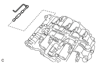
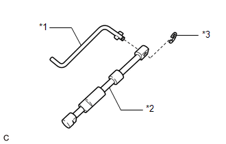
1. REMOVE MANUAL VALVE
| (a) Remove the manual valve from the transmission valve body assembly. |
|
| (b) Remove the E-ring and separate the manual valve connecting rod from the manual valve. |
|
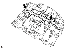
2. REMOVE SOLENOID LOCK PLATE
| (a) Remove the 2 bolts and solenoid lock plate from the transmission valve body assembly. |
|
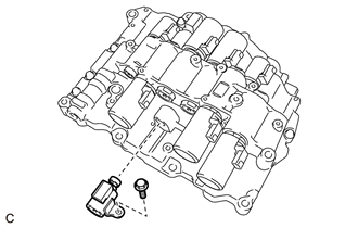
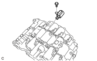
3. REMOVE SHIFT SOLENOID VALVE S1
| (a) Remove the bolt and shift solenoid valve S1. |
|
4. REMOVE SHIFT SOLENOID VALVE S2
| (a) Remove the bolt and shift solenoid valve S2. |
|
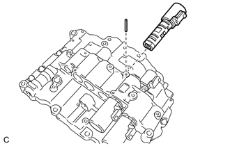
5. REMOVE SHIFT SOLENOID VALVE SLU
| (a) Using a Magnet Hand, remove the straight pin from the transmission valve body assembly. |
|
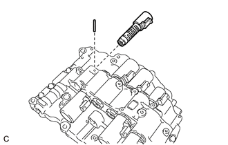
(b) Remove the shift solenoid valve SLU from the transmission valve body assembly.
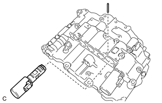
6. REMOVE SHIFT SOLENOID VALVE SL1
| (a) Using a Magnet Hand, remove the straight pin from the transmission valve body assembly. |
|
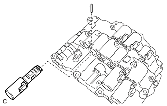
(b) Remove the shift solenoid valve SL1 from the transmission valve body assembly.
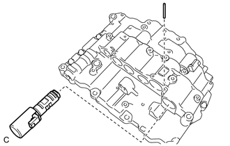
7. REMOVE SHIFT SOLENOID VALVE SL2
| (a) Using a Magnet Hand, remove the straight pin from the transmission valve body assembly. |
|
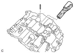
(b) Remove the shift solenoid valve SL2 from the transmission valve body assembly.
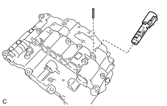
8. REMOVE SHIFT SOLENOID VALVE SL3
| (a) Using a Magnet Hand, remove the straight pin from the transmission valve body assembly. |
|
(b) Remove the shift solenoid valve SL3 from the transmission valve body assembly.
9. REMOVE SHIFT SOLENOID VALVE SL4
| (a) Using a Magnet Hand, remove the straight pin from the transmission valve body assembly. |
|
(b) Remove the shift solenoid valve SL4 from the transmission valve body assembly.
10. REMOVE SHIFT SOLENOID VALVE SL5
| (a) Using a Magnet Hand, remove the straight pin from the transmission valve body assembly. |
|
(b) Remove the shift solenoid valve SL5 from the transmission valve body assembly.
11. REMOVE SHIFT SOLENOID VALVE SLT
| (a) Using a Magnet Hand, remove the straight pin from the transmission valve body assembly. |
|
(b) Remove the shift solenoid valve SLT from the transmission valve body assembly.
 Removal
REMOVAL CAUTION / NOTICE / HINT The necessary procedures (adjustment, calibration, initialization or registration) that must be performed after parts are removed and installed, or replaced during tran ...
 Inspection
INSPECTION PROCEDURE 1. INSPECT SHIFT SOLENOID VALVE S1 (a) Measure the resistance according to the value(s) in the table below. Standard Resistance: Tester Connection Condition Specified C ...
Other materials:
Lexus RX (RX 350L, RX450h) 2016-2026 Repair Manual > Cornering Light Assembly: Components
COMPONENTS ILLUSTRATION *A w/ Headlight Cleaner System *B for LH Side *C for Type A *D for Type B *1 CORNERING LIGHT ASSEMBLY (FOG LIGHT ASSEMBLY) *2 FRONT BUMPER ARM HOLE COVER LH *3 HEADLIGHT CLEANER HOSE - - ...
Lexus RX (RX 350L, RX450h) 2016-2026 Repair Manual > Heated Steering Wheel System: How To Proceed With Troubleshooting
CAUTION / NOTICE / HINT HINT: Use these procedures to troubleshoot the heated steering wheel system. PROCEDURE 1. VEHICLE BROUGHT TO WORKSHOP
NEXT 2. INSPECT BATTERY VOLTAGE Standard Voltage: 11 to 14 V If the voltage is below 11 V, recharge or replace the battery ...
Lexus RX (RX 350L, RX450h) 2016-{YEAR} Owners Manual
- For your information
- Pictorial index
- For safety and security
- Instrument cluster
- Operation of each component
- Driving
- Lexus Display Audio system
- Interior features
- Maintenance and care
- When trouble arises
- Vehicle specifications
- For owners
Lexus RX (RX 350L, RX450h) 2016-{YEAR} Repair Manual

0.0097