Lexus RX (RX 350L, RX450h) 2016-2026 Repair Manual: Steering Pad Switch Circuit
DESCRIPTION
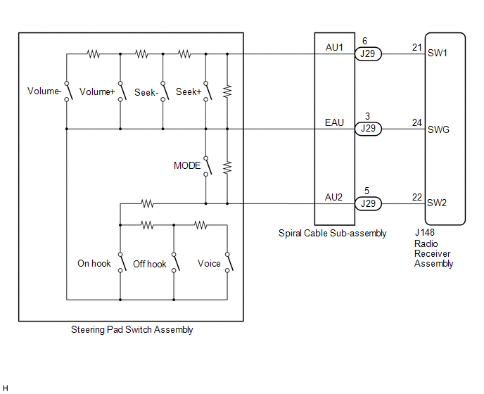
This circuit sends an operation signal from the steering pad switch assembly to the radio receiver assembly.
If there is an open in the circuit, the navigation system cannot be operated using the steering pad switch assembly.
If there is a short in the circuit, the same condition as when a switch is continuously depressed occurs.
Therefore, the radio receiver assembly cannot be operated using the steering pad switch assembly, also the radio receiver assembly itself will not function.
WIRING DIAGRAM
CAUTION / NOTICE / HINT
NOTICE:
The vehicle is equipped with a Supplemental Restraint System (SRS) which includes components such as airbags. Before servicing (including removal or installation of parts), be sure to read the precaution for Supplemental Restraint System.
Click here .gif)
PROCEDURE
| 1. | INSPECT STEERING PAD SWITCH ASSEMBLY |
(a) Remove the steering pad switch assembly.
Click here
(b) Inspect the steering pad switch assembly.
Click here
| NG | .gif) | REPLACE STEERING PAD SWITCH ASSEMBLY |
|
.gif)
| 2. | INSPECT SPIRAL CABLE SUB-ASSEMBLY |
(a) Remove the spiral cable sub-assembly.
Click here
(b) Inspect the spiral cable sub-assembly.
Click here
| NG | | REPLACE SPIRAL CABLE SUB-ASSEMBLY |
|
| 3. | CHECK HARNESS AND CONNECTOR (STEERING PAD SWITCH SIGNAL) |
(a) Disconnect the J148 radio receiver assembly connector.
(b) Disconnect the J29 spiral cable sub-assembly connector.
(c) Measure the resistance according to the value(s) in the table below.
Standard Resistance:
| Tester Connection | Condition | Specified Condition |
|---|---|---|
| J148-21 (SW1) - J29-6 (AU1) | Always | Below 1 Ω |
| J148-22 (SW2) - J29-5 (AU2) | Always | Below 1 Ω |
| J148-24 (SWG) - J29-3 (EAU) | Always | Below 1 Ω |
| J148-21 (SW1) or J29-6 (AU1) - Body ground | Always | 10 kΩ or higher |
| J148-22 (SW2) or J29-5 (AU2) - Body ground | Always | 10 kΩ or higher |
| J148-24 (SWG) or J29-3 (EAU) - Body ground | Always | 10 kΩ or higher |
| OK | | PROCEED TO NEXT SUSPECTED AREA SHOWN IN PROBLEM SYMPTOMS TABLE |
| NG | | REPAIR OR REPLACE HARNESS OR CONNECTOR (RADIO RECEIVER ASSEMBLY - SPIRAL CABLE SUB-ASSEMBLY) |
 Black Screen
PROCEDURE 1. CHECK DISPLAY SETTING (a) Check that the display is not in screen off mode. OK: The display setting is not in screen off mode. NG CHANGE SCREEN TO SCREEN ON MODE
...
 Illumination Circuit
DESCRIPTION Power is supplied to the radio receiver assembly and steering pad switch assembly illumination when the light control switch is in the tail or head position. WIRING DIAGRAM CAUTION / NOTI ...
Other materials:
Lexus RX (RX 350L, RX450h) 2016-2026 Repair Manual > Automatic Transaxle System: Pressure Control Solenoid "H" Actuator Stuck Off (P28167F)
DESCRIPTION Based on signals from the transmission revolution sensors (NT, NC3 and NC), the actual gear is detected. The ECM compares the actual gear with the shift schedule in the ECM memory to detect mechanical malfunctions of the shift solenoid valves, transmission valve body assembly and automat ...
Lexus RX (RX 350L, RX450h) 2016-2026 Repair Manual > Fuel Injector (for Port Injection): Components
COMPONENTS ILLUSTRATION *1 FUEL DELIVERY PIPE SUB-ASSEMBLY *2 FUEL INJECTOR ASSEMBLY *3 FUEL TUBE SUB-ASSEMBLY *4 INJECTOR VIBRATION INSULATOR *5 NO. 1 DELIVERY PIPE SPACER *6 NO. 5 ENGINE WIRE (for Bank 1) *7 NO. 5 ENGINE WIRE (for Bank 2) *8 O-RING Ti ...
Lexus RX (RX 350L, RX450h) 2016-{YEAR} Owners Manual
- For your information
- Pictorial index
- For safety and security
- Instrument cluster
- Operation of each component
- Driving
- Lexus Display Audio system
- Interior features
- Maintenance and care
- When trouble arises
- Vehicle specifications
- For owners
Lexus RX (RX 350L, RX450h) 2016-{YEAR} Repair Manual

0.0114