Lexus RX (RX 350L, RX450h) 2016-2026 Repair Manual: Illumination Circuit
DESCRIPTION
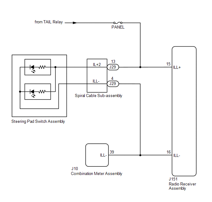
Power is supplied to the radio receiver assembly and steering pad switch assembly illumination when the light control switch is in the tail or head position.
WIRING DIAGRAM
CAUTION / NOTICE / HINT
NOTICE:
-
The vehicle is equipped with a Supplemental Restraint System (SRS) which includes components such as airbags. Before servicing (including removal or installation of parts), be sure to read the precaution for Supplemental Restraint System.
Click here
.gif)
- Inspect the fuses for circuits related to this system before performing the following procedure.
PROCEDURE
| 1. | CHECK ILLUMINATION |
(a) Check if the illumination for the radio receiver assembly, steering pad switch assembly, heater control switch or others (hazard switch, transmission control switch, etc.) comes on when the light control switch is turned to the head or tail position.
| Result | Proceed to |
|---|---|
| Illumination comes on for all components except steering pad switch assembly. | A |
| Illumination comes on for all components except radio receiver assembly. | B |
| No illumination comes on (radio receiver assembly, hazard switch, heater control switch, etc.). | C |
| B | .gif) | GO TO STEP 5 |
| C | | GO TO LIGHTING SYSTEM |
|
.gif)
| 2. | CHECK HARNESS AND CONNECTOR (ILLUMINATION SIGNAL) |
(a) Disconnect the J29 spiral cable sub-assembly connector.
(b) Measure the voltage according to the value(s) in the table below.
Standard Voltage:
| Tester Connection | Condition | Specified Condition |
|---|---|---|
| J29-13 (IL+2) - Body ground | Light control switch in tail or head position | 11 to 14 V |
| NG | | REPAIR OR REPLACE HARNESS OR CONNECTOR |
|
| 3. | INSPECT STEERING PAD SWITCH ASSEMBLY |
(a) Remove the steering pad switch assembly.
Click here
(b) Inspect the steering pad switch assembly.
Click here
| NG | | REPLACE STEERING PAD SWITCH ASSEMBLY |
|
| 4. | INSPECT SPIRAL CABLE SUB-ASSEMBLY |
(a) Remove the spiral cable sub-assembly.
Click here
(b) Inspect the spiral cable sub-assembly.
Click here
| OK | | REPAIR OR REPLACE HARNESS OR CONNECTOR (SPIRAL CABLE SUB-ASSEMBLY - RADIO RECEIVER ASSEMBLY, COMBINATION METER ASSEMBLY) |
| NG | | REPLACE SPIRAL CABLE SUB-ASSEMBLY |
| 5. | CHECK HARNESS AND CONNECTOR (ILLUMINATION SIGNAL) |
(a) Disconnect the J151 radio receiver assembly connector.
(b) Measure the voltage according to the value(s) in the table below.
Standard Voltage:
| Tester Connection | Condition | Specified Condition |
|---|---|---|
| J151-15 (ILL+) - Body ground | Light control switch in tail or head position | 11 to 14 V |
| NG | | REPAIR OR REPLACE HARNESS OR CONNECTOR |
|
| 6. | CHECK HARNESS AND CONNECTOR (RADIO RECEIVER ASSEMBLY - COMBINATION METER ASSEMBLY) |
(a) Disconnect the J151 radio receiver assembly connector.
(b) Disconnect the J10 combination meter assembly connector.
(c) Measure the resistance according to the value(s) in the table below.
Standard Resistance:
| Tester Connection | Condition | Specified Condition |
|---|---|---|
| J151-16 (ILL-) - J10-39 (ILL-) | Always | Below 1 Ω |
| J151-16 (ILL-) or J10-39 (ILL-) - Body ground | Always | 10 kΩ or higher |
| OK | | PROCEED TO NEXT SUSPECTED AREA SHOWN IN PROBLEM SYMPTOMS TABLE |
| NG | | REPAIR OR REPLACE HARNESS OR CONNECTOR |
 Steering Pad Switch Circuit
DESCRIPTION This circuit sends an operation signal from the steering pad switch assembly to the radio receiver assembly. If there is an open in the circuit, the navigation system cannot be operated us ...
 Sound Signal Circuit between Radio Receiver and Stereo Jack Adapter
DESCRIPTION The No. 1 stereo jack adapter assembly sends the sound signal from an external device to the radio receiver assembly via this circuit. WIRING DIAGRAM PROCEDURE 1. CHECK HARNESS AND ...
Other materials:
Lexus RX (RX 350L, RX450h) 2016-2026 Repair Manual > Back Door Closer Ecu: Removal
REMOVAL CAUTION / NOTICE / HINT The necessary procedures (adjustment, calibration, initialization, or registration) that must be performed after parts are removed and installed, or replaced during back door closer ECU removal/installation are shown below. Necessary Procedure After Parts Removed/Inst ...
Lexus RX (RX 350L, RX450h) 2016-2026 Repair Manual > Front Seatback Heater: Installation
INSTALLATION CAUTION / NOTICE / HINT CAUTION: Wear protective gloves. Sharp areas on the parts may injure your hands. HINT:
Use the same procedure for the RH side and LH side.
The following procedure is for the LH side.
PROCEDURE 1. INSTALL FRONT SEATBACK HEATER ASSEMBLY (for Standard Seat T ...
Lexus RX (RX 350L, RX450h) 2016-{YEAR} Owners Manual
- For your information
- Pictorial index
- For safety and security
- Instrument cluster
- Operation of each component
- Driving
- Lexus Display Audio system
- Interior features
- Maintenance and care
- When trouble arises
- Vehicle specifications
- For owners
Lexus RX (RX 350L, RX450h) 2016-{YEAR} Repair Manual

0.0126