Lexus RX (RX 350L, RX450h) 2016-2026 Repair Manual: Mute Signal Circuit between Stereo Component Amplifier and Telematics Transceiver
DESCRIPTION
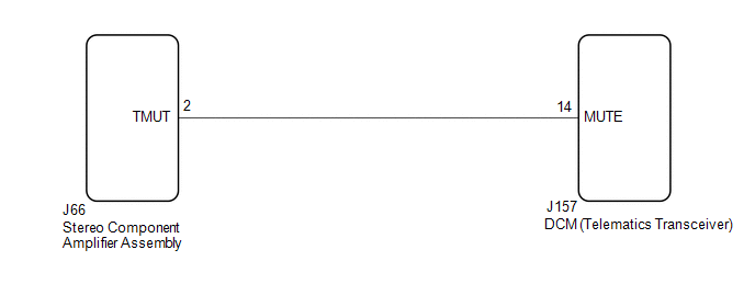
The DCM (telematics transceiver) sends a mute signal to the stereo component amplifier assembly.
The stereo component amplifier assembly controls the volume according to the mute signal from the DCM (telematics transceiver).
WIRING DIAGRAM
CAUTION / NOTICE / HINT
NOTICE:
-
Depending on the parts that are replaced during vehicle inspection or maintenance, performing initialization, registration or calibration may be needed. Refer to Precaution for Navigation System.
Click here
.gif)
-
Before replacing the DCM (telematics transceiver), refer to Registration.
Click here
PROCEDURE
| 1. | INSPECT DCM (TELEMATICS TRANSCEIVER) |
| (a) Measure the voltage according to the value(s) in the table below. Standard Voltage:
|
|
| OK |  | PROCEED TO NEXT SUSPECTED AREA SHOWN IN PROBLEM SYMPTOMS TABLE |
|

| 2. | CHECK HARNESS AND CONNECTOR (STEREO COMPONENT AMPLIFIER ASSEMBLY - DCM (TELEMATICS TRANSCEIVER)) |
(a) Disconnect the J66 stereo component amplifier assembly connector.
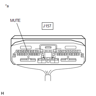
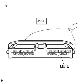
(b) Disconnect the J157 DCM (telematics transceiver) connector.
(c) Measure the resistance according to the value(s) in the table below.
Standard Resistance:
| Tester Connection | Condition | Specified Condition |
|---|---|---|
| J66-2 (TMUT) - J157-14 (MUTE) | Always | Below 1 Ω |
| J66-2 (TMUT) or J157-14 (MUTE) - Body ground | Always | 10 kΩ or higher |
| NG | | REPAIR OR REPLACE HARNESS AND CONNECTOR |
|
| 3. | INSPECT STEREO COMPONENT AMPLIFIER ASSEMBLY |
(a) Reconnect the J66 stereo component amplifier assembly connector.
| (b) Measure the voltage according to the value(s) in the table below. Standard Voltage:
|
|
| OK | | REPLACE DCM (TELEMATICS TRANSCEIVER) |
| NG | | REPLACE STEREO COMPONENT AMPLIFIER ASSEMBLY |
 Data Signal Circuit between Radio Receiver and Stereo Jack Adapter
DESCRIPTION The No. 1 stereo jack adapter assembly sends the sound data signal or image data signal from a USB device to the radio receiver assembly via this circuit. WIRING DIAGRAM PROCEDURE 1. ...
 AVC-LAN Circuit
DESCRIPTION Each unit of the navigation system connected to the AVC-LAN (communication bus) transmits switch signals via AVC-LAN communication. If a short to +B or short to ground occurs in the AVC-LA ...
Other materials:
Lexus RX (RX 350L, RX450h) 2016-2026 Owners Manual > Adjusting the steering wheel and mirrors: Inside rear view mirror
The rear view mirror's position can be adjusted to enable sufficient
confirmation
of the rear view.
Adjusting the height of rear view mirror
The height of the rear view mirror can be adjusted to suit your driving
posture.
Adjust the height of the rear view mirror
by moving it up and down. ...
Lexus RX (RX 350L, RX450h) 2016-2026 Repair Manual > Power Seat Switch(w/ Seat Position Memory System): Installation
INSTALLATION CAUTION / NOTICE / HINT CAUTION: Wear protective gloves. Sharp areas on the parts may injure your hands. PROCEDURE 1. INSTALL POSITION CONTROL ECU AND SWITCH ASSEMBLY LH (a) Install the position control ECU and switch assembly LH to the front seat cushion shield LH with the 3 screws. ...
Lexus RX (RX 350L, RX450h) 2016-{YEAR} Owners Manual
- For your information
- Pictorial index
- For safety and security
- Instrument cluster
- Operation of each component
- Driving
- Lexus Display Audio system
- Interior features
- Maintenance and care
- When trouble arises
- Vehicle specifications
- For owners
Lexus RX (RX 350L, RX450h) 2016-{YEAR} Repair Manual

0.0097