Lexus RX (RX 350L, RX450h) 2016-2026 Repair Manual: Vehicle Speed Signal Circuit between Stereo Component Amplifier and Combination Meter
DESCRIPTION
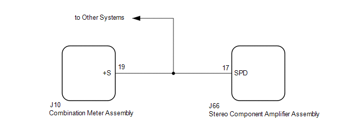
The stereo component amplifier assembly receives a vehicle speed signal from the combination meter assembly to control the ASL function.
HINT:
- A voltage of 12 V or 5 V is output from each ECU and then input to the combination meter assembly. The signal is changed to a pulse signal at the transistor in the combination meter assembly. Each ECU controls its respective systems based on this pulse signal.
- If a short occurs in any of the ECUs or in the wire harness connected to an ECU, all systems in the following diagram will not operate normally.
WIRING DIAGRAM
PROCEDURE
| 1. | INSPECT COMBINATION METER ASSEMBLY (OUTPUT WAVEFORM) |
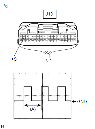
| (a) Check the output waveform. (1) Remove the combination meter assembly with the connector(s) still connected. (2) Connect an oscilloscope to terminal J10-19 (+S) and body ground. (3) Turn the engine switch on (IG). (4) Turn a wheel slowly. (5) Check the signal waveform according to the condition(s) in the table below.
OK: The waveform is similar to that shown in the illustration. HINT: When the system is functioning normally, one wheel revolution generates 4 pulses. As the vehicle speed increases, the width indicated by (A) in the illustration narrows. |
|
| NG |  | GO TO METER / GAUGE SYSTEM |
|

| 2. | INSPECT STEREO COMPONENT AMPLIFIER ASSEMBLY (INPUT WAVEFORM) |
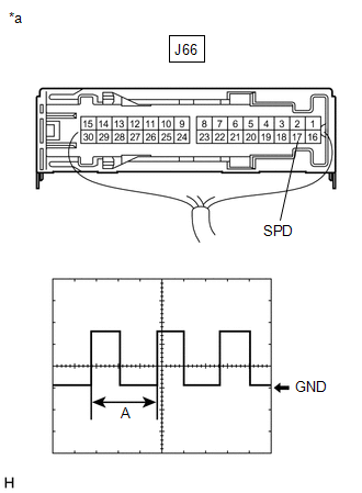
| (a) Check the input waveform. (1) Remove the stereo component amplifier assembly with the connector(s) still connected. (2) Connect an oscilloscope to terminal J66-17 (SPD) and body ground. (3) Turn the engine switch on (IG). (4) Turn a wheel slowly. (5) Check the signal waveform according to the condition(s) in the table below.
OK: The waveform is similar to that shown in the illustration. HINT: When the system is functioning normally, one wheel revolution generates 4 pulses. As the vehicle speed increases, the width indicated by (A) in the illustration narrows. |
|
| OK | | PROCEED TO NEXT SUSPECTED AREA SHOWN IN PROBLEM SYMPTOMS TABLE |
| NG | | REPAIR OR REPLACE HARNESS OR CONNECTOR |
 Vehicle Speed Signal Circuit between Navigation ECU and Combination Meter
DESCRIPTION The navigation ECU receives a vehicle speed signal from the combination meter assembly. HINT:
A voltage of 12 V or 5 V is output from each ECU and then input to the combination meter as ...
 Reverse Signal Circuit between Radio Receiver Assembly and Navigation ECU
DESCRIPTION This circuit includes the navigation ECU and radio receiver assembly. WIRING DIAGRAM PROCEDURE 1. CHECK HARNESS AND CONNECTOR (RADIO RECEIVER ASSEMBLY - NAVIGATION ECU) (a) Disco ...
Other materials:
Lexus RX (RX 350L, RX450h) 2016-2026 Repair Manual > Sfi System: Fuel Level Sensor "A" Signal Stuck In Range (P04602A)
DESCRIPTION Refer to DTC P046012. Click here DTC No. Detection Item DTC Detection Condition Trouble Area MIL Memory Note P04602A Fuel Level Sensor "A" Signal Stuck In Range The change in the fuel sender gauge value is below the threshold when a certain amount of fuel is calc ...
Lexus RX (RX 350L, RX450h) 2016-2026 Repair Manual > Power Mirror Control System (w/ Memory): Problem Symptoms Table
PROBLEM SYMPTOMS TABLE NOTICE: If the battery voltage is low, the mirror heater function may not operate. When "Operation of Electrical Items Restricted." is displayed on the multi-information display in the combination meter assembly, check the Data List item "Battery Control Count (Body ECU)". Cli ...
Lexus RX (RX 350L, RX450h) 2016-{YEAR} Owners Manual
- For your information
- Pictorial index
- For safety and security
- Instrument cluster
- Operation of each component
- Driving
- Lexus Display Audio system
- Interior features
- Maintenance and care
- When trouble arises
- Vehicle specifications
- For owners
Lexus RX (RX 350L, RX450h) 2016-{YEAR} Repair Manual

0.0122