Lexus RX (RX 350L, RX450h) 2016-2026 Repair Manual: Terminals Of Ecu
TERMINALS OF ECU
CLEARANCE WARNING ECU ASSEMBLY

(a) Disconnect the J38 clearance warning ECU assembly connector.
(b) Measure the voltage and resistance on the wire harness side connector according to the value(s) in the table below.
| Terminal No. (Symbol) | Wiring Color | Terminal Description | Condition | Specified Condition |
|---|---|---|---|---|
| J38-1 (IG) - J38-30 (E) | SB - W-B | IG power source signal | Engine switch off | Below 1 V |
| Engine switch on (IG) | 11 to 14 V | |||
| J38-30 (E) - Body ground | W-B - Body ground | Ground | Always | Below 1 Ω |
(c) Reconnect the J38 clearance warning ECU assembly connector.
(d) Measure the voltage and resistance and check for pulses according to the value(s) in the table below.
| Terminal No. (Symbol) | Wiring Color | Terminal Description | Condition | Specified Condition |
|---|---|---|---|---|
| J38-4 (BOF) - J38-30 (E) | P - W-B | Power source for front sensor circuit | Engine switch off | Below 1 V |
| 11 to 14 V | |||
| J38-6 (E5) - J38-30 (E) | L - W-B | Ground for front clearance sonar | Always | Below 1 Ω |
| J38-8 (SOF) - J38-30 (E) | B - W-B | Front sensor communication signal (Front clearance sonar sensor) |
| Pulse generation (Refer to waveform 1) |
| J38-14 (CBZ) - J38-13 (EF) | Y - P | No. 1 clearance warning buzzer signal | Buzzer sounding | Pulse generation (Refer to waveform 2) |
| J38-15 (BBZ) - J38-16 (ER) | R - W | No. 2 clearance warning buzzer signal | Buzzer sounding | Pulse generation (Refer to waveform 2) |
| J38-22 (BOR) - J38-30 (E) | LG - W-B | Power source for rear sensor circuit | Engine switch off | Below 1 V |
| 11 to 14 V | |||
| J38-23 (E1) - J38-30 (E) | GR - W-B | Ground for rear clearance sonar | Always | Below 1 Ω |
| J38-24 (SOR) - J38-30 (E) | SB - W-B | Rear sensor communication signal (Rear clearance sonar sensor) |
| Pulse generation (Refer to waveform 3) |
(e) Using an oscilloscope, check waveform 1.
(1) Waveform 1 (Reference)
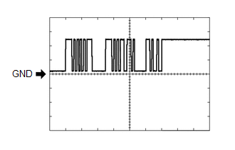
| Item | Content |
|---|---|
| Measurement terminal | J38-8 (SOF) - J38-30 (E) |
| Measurement setting | 5 V/DIV., 1 ms./DIV. |
| Condition |
|
(f) Using an oscilloscope, check waveform 2.
(1) Waveform 2 (Reference)
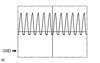
| Item | Content |
|---|---|
| Measurement terminal |
|
| Measurement setting | 2 V/DIV., 500 μs./DIV. |
| Condition | Buzzer sounding |
HINT:
The amplitude of the waveform changes according to the set volume.
(g) Using an oscilloscope, check waveform 3.
(1) Waveform 3 (Reference)
| Item | Content |
|---|---|
| Measurement terminal | J38-24 (SOR) - J38-30 (E) |
| Measurement setting | 5 V/DIV., 1 ms./DIV. |
| Condition |
|
ECM
Click here .gif)
COMBINATION METER ASSEMBLY
Click here
 Problem Symptoms Table
PROBLEM SYMPTOMS TABLE HINT:
Use the table below to help determine the cause of problem symptoms. If multiple suspected areas are listed, the potential causes of the symptoms are listed in order of ...
 Diagnosis System
DIAGNOSIS SYSTEM DESCRIPTION (a) Intelligent clearance sonar system data and Diagnostic Trouble Codes (DTCs) can be read from the Data Link Connector 3 (DLC3) of the vehicle. When the system seems to ...
Other materials:
Lexus RX (RX 350L, RX450h) 2016-2026 Repair Manual > Fuel Sender Gauge Assembly: Components
COMPONENTS ILLUSTRATION *A for TMC Made - - *1 FUEL SENDER GAUGE ASSEMBLY *2 FUEL SUCTION TUBE WITH PUMP AND GAUGE ASSEMBLY ILLUSTRATION *A for TMMC Made - - *1 FUEL SENDER GAUGE ASSEMBLY *2 FUEL SUCTION TUBE WITH PUMP AND GAUGE ASSEMBLY ...
Lexus RX (RX 350L, RX450h) 2016-2026 Repair Manual > Luggage Speaker (w/o Rear No. 2 Seat): Components
COMPONENTS ILLUSTRATION *A for TMC Made *B for TMMC Made *1 DECK BOARD ASSEMBLY *2 DECK SIDE TRIM BOX RH *3 FRONT DECK FLOOR BOX *4 REAR DECK FLOOR BOX *5 REAR FLOOR FINISH PLATE *6 REAR NO. 3 FLOOR BOARD *7 REAR NO. 4 FLOOR BOARD *8 TONNEAU COVER AS ...
Lexus RX (RX 350L, RX450h) 2016-{YEAR} Owners Manual
- For your information
- Pictorial index
- For safety and security
- Instrument cluster
- Operation of each component
- Driving
- Lexus Display Audio system
- Interior features
- Maintenance and care
- When trouble arises
- Vehicle specifications
- For owners
Lexus RX (RX 350L, RX450h) 2016-{YEAR} Repair Manual

0.0167