Lexus RX (RX 350L, RX450h) 2016-2026 Repair Manual: Back Camera Power Supply Failure (C1621)
DESCRIPTION
This DTC is stored if the rear television camera assembly judges as a result of its self check that the signals or signal lines between the rear television camera assembly and multi-display assembly are not normal.
| DTC No. | Detection Item | DTC Detection Condition | Trouble Area |
|---|---|---|---|
| C1621 | Back Camera Power Supply Failure | Rear television camera assembly power supply failure |
|
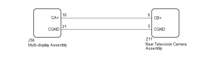
WIRING DIAGRAM
CAUTION / NOTICE / HINT
NOTICE:
-
When "!" mark is displayed on the multi-display assembly after disconnecting the cable from the negative (-) battery terminal, correct the steering angle neutral point.
Click here
.gif)
-
Depending on the parts that are replaced or operations that are performed during vehicle inspection or maintenance, calibration of other systems as well as the parking assist monitor system may be needed.
Click here
PROCEDURE
| 1. | CHECK HARNESS AND CONNECTOR (MULTI-DISPLAY ASSEMBLY - REAR TELEVISION CAMERA ASSEMBLY) |
(a) Disconnect the J56 multi-display assembly connector.
(b) Disconnect the Z11 rear television camera assembly connector.
(c) Measure the resistance according to the value(s) in the table below.
Standard Resistance:
| Tester Connection | Condition | Specified Condition |
|---|---|---|
| J56-10 (CA+) - Z11-6 (CB+) | Always | Below 1 Ω |
| J56-21 (CGND) - Z11-5 (CGND) | Always | Below 1 Ω |
| J56-10 (CA+) or Z11-6 (CB+) - Body ground | Always | 10 kΩ or higher |
| J56-21 (CGND) or Z11-5 (CGND) - Body ground | Always | 10 kΩ or higher |
| NG | .gif) | REPAIR OR REPLACE HARNESS OR CONNECTOR |
|
.gif)
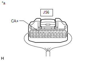
| 2. | INSPECT MULTI-DISPLAY ASSEMBLY (CA+) |
(a) Reconnect the J56 multi-display assembly connector.
| (b) Measure the voltage according to the value(s) in the table below. Standard Voltage:
|
|
| OK | | REPLACE REAR TELEVISION CAMERA ASSEMBLY |
| NG | | REPLACE MULTI-DISPLAY ASSEMBLY |
 ECU Malfunction (C1611)
DESCRIPTION This DTC is stored if the rear television camera assembly judges that there is an internal malfunction as a result of its self check. HINT: The rear television camera assembly stores diffe ...
 Open or Short in Steering Angle Sensor +B (C1625)
DESCRIPTION This DTC is stored if the rear television camera assembly receives a signal via CAN communication from the steering sensor that indicates a power supply problem. DTC No. Detection Ite ...
Other materials:
Lexus RX (RX 350L, RX450h) 2016-2026 Repair Manual > Smart Access System With Push-button Start (for Entry Function): Rear Door LH Entry Unlock Function does not Operate
DESCRIPTION If the entry unlock function does not operate for the rear door LH only, but the entry lock function operates, the request code is being transmitted properly from the rear door LH. In this case, there may be a problem related to the unlock sensor (connection between the certification ECU ...
Lexus RX (RX 350L, RX450h) 2016-2026 Repair Manual > Parking Assist Monitor System: System Diagram
SYSTEM DIAGRAM Communication Table Sender Receiver Signal Line Multi-display Assembly Radio Receiver Assembly Camera information signal GVIF Radio Receiver Assembly Rear Television Camera Assembly Camera information signal CAN Steering Sensor Rear Television Came ...
Lexus RX (RX 350L, RX450h) 2016-{YEAR} Owners Manual
- For your information
- Pictorial index
- For safety and security
- Instrument cluster
- Operation of each component
- Driving
- Lexus Display Audio system
- Interior features
- Maintenance and care
- When trouble arises
- Vehicle specifications
- For owners
Lexus RX (RX 350L, RX450h) 2016-{YEAR} Repair Manual

0.0095