Lexus RX (RX 350L, RX450h) 2016-2026 Repair Manual: Television Camera (for Front)
Components
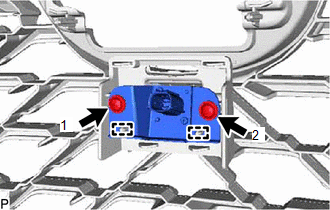
COMPONENTS
ILLUSTRATION
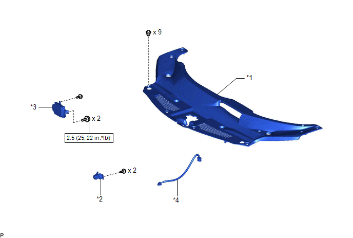
| *1 | COOL AIR INTAKE DUCT SEAL | *2 | FRONT TELEVISION CAMERA ASSEMBLY |
| *3 | MILLIMETER WAVE RADAR SENSOR ASSEMBLY | *4 | TELEVISION CAMERA WIRE |
.png) | N*m (kgf*cm, ft.*lbf): Specified torque | - | - |
Removal
REMOVAL
CAUTION / NOTICE / HINT
The necessary procedures (adjustment, calibration, initialization, or registration) that must be performed after parts are removed and installed, or replaced during front television camera assembly removal/installation are shown below.
Necessary Procedure After Parts Removed/Installed/Replaced| Replaced Part or Performed Procedure | Necessary Procedure | Effect/Inoperative Function when Necessary Procedure not Performed | Link |
|---|---|---|---|
| Front television camera assembly | Front television camera view adjustment | Panoramic view monitor system | |
PROCEDURE
1. PRECAUTION
Click here .gif)
2. REMOVE COOL AIR INTAKE DUCT SEAL
Click here
3. REMOVE MILLIMETER WAVE RADAR SENSOR ASSEMBLY
Click here
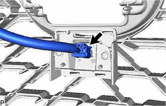
4. REMOVE FRONT TELEVISION CAMERA ASSEMBLY
| (a) Disconnect the connector. |
|
| (b) Remove the 2 screws. |
|
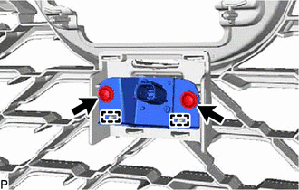
(c) Disengage the 2 guides and remove the front television camera assembly.
5. REMOVE TELEVISION CAMERA WIRE
HINT:
Perform this procedure only when replacement of the television camera wire is necessary.
| (a) Disconnect the connector and remove the television camera wire. |
|
Installation
INSTALLATION
PROCEDURE
1. INSTALL TELEVISION CAMERA WIRE
HINT:
Perform this procedure only when replacement of the television camera wire is necessary.
(a) Connect the connector to install the television camera wire.
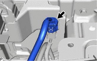
2. INSTALL FRONT TELEVISION CAMERA ASSEMBLY
| (a) Engage the 2 guides. |
|
(b) Install the front television camera assembly with the 2 screws.
HINT:
Install the screws in the order shown in the illustration.
(c) Connect the connector.
3. INSTALL MILLIMETER WAVE RADAR SENSOR ASSEMBLY
Click here .gif)
4. INSTALL COOL AIR INTAKE DUCT SEAL
Click here
5. PERFORM INITIALIZATION
Click here
6. ADJUST FRONT TELEVISION CAMERA ASSEMBLY
Click here
 Removal
REMOVAL CAUTION / NOTICE / HINT The necessary procedures (adjustment, calibration, initialization, or registration) that must be performed after parts are removed and installed, or replaced during bli ...

Other materials:
Lexus RX (RX 350L, RX450h) 2016-2026 Repair Manual > Condenser: Components
COMPONENTS ILLUSTRATION *1 HOOD LOCK ASSEMBLY *2 HOOD LOCK CONTROL CABLE COVER *3 HOOD LOCK RELEASE LEVER PROTECTOR *4 INLET AIR CLEANER ASSEMBLY *5 UPPER RADIATOR SUPPORT SUB-ASSEMBLY - - N*m (kgf*cm, ft.*lbf): Specified torque * For use with a union nut wre ...
Lexus RX (RX 350L, RX450h) 2016-2026 Repair Manual > Audio And Visual System (for 12.3 Inch Display): Air Conditioner ECU Vehicle Information Reading/Writing Processor Malfunction (B15F5)
DESCRIPTION This DTC is stored when items controlled by the air conditioning amplifier assembly cannot be customized via the audio and visual system vehicle customization screen. HINT: The air conditioning amplifier assembly controls the air conditioning system related items that are customizable vi ...
Lexus RX (RX 350L, RX450h) 2016-{YEAR} Owners Manual
- For your information
- Pictorial index
- For safety and security
- Instrument cluster
- Operation of each component
- Driving
- Lexus Display Audio system
- Interior features
- Maintenance and care
- When trouble arises
- Vehicle specifications
- For owners
Lexus RX (RX 350L, RX450h) 2016-{YEAR} Repair Manual

0.012